Hi all, I've just ordered Brian's LM3886 dual-mono kit from Chipamp.com and a 160VA 2x25V Toroid. I've been planning out how to build it. Please be patient with me as rather noob.
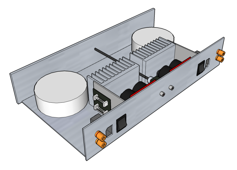
Here's a few pics of one of my ideas, I was hoping for some C&C regarding placement of things and potential problems/improvements. Keep in mind I currently only have a single toroid, so ignore the second toroid in the pictures.
Also any ideas into actually MAKING the damn box would be greatly appreciated too, as although I've done some metalwork for PC cases I don't have any special tools and I'm hardly skilled. I have a stack of 2.5mm aluminium panels and I have one 500x90x6mm piece for my frontpanel.
Another query... does anyone know where to get a good audio potentiometer in Aus.?? I have a few 10k stereo pots in my junk box, but I have no idea if they're any good.
And yet another, can I use my "Delta Electronics" EMI filtered IEC socket?? Will it actually be beneficial or am I better off using a standard socket (e.g. one from an old PC PSU)?
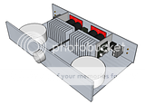
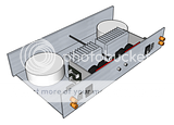
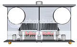
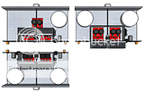
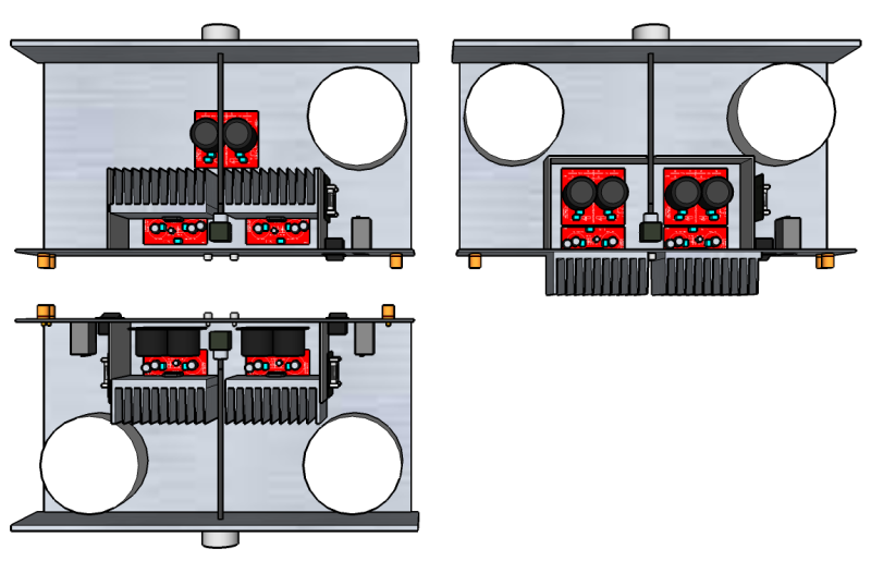
Here are my three basic plans, not sure which is best... all have pot near amps to minimise the length of the signal path.
1. Stereo setup, internal heatsinks for chips providing interference shielding from mains/toroid.
2. Dual-mono setup, external heatsinks for chips. PSU boards next to amp boards. Aluminium panels provide shielding from mains/toroid interference.
3. Dual-mono setup, internal heatsinks for chips provide shielding from mains/toroid interference. PSU boards 90° to amps on backpanel. (As per above pics).
Thanks all!!
--
Nathan
Here's a few pics of one of my ideas, I was hoping for some C&C regarding placement of things and potential problems/improvements. Keep in mind I currently only have a single toroid, so ignore the second toroid in the pictures.
Also any ideas into actually MAKING the damn box would be greatly appreciated too, as although I've done some metalwork for PC cases I don't have any special tools and I'm hardly skilled. I have a stack of 2.5mm aluminium panels and I have one 500x90x6mm piece for my frontpanel.
Another query... does anyone know where to get a good audio potentiometer in Aus.?? I have a few 10k stereo pots in my junk box, but I have no idea if they're any good.
And yet another, can I use my "Delta Electronics" EMI filtered IEC socket?? Will it actually be beneficial or am I better off using a standard socket (e.g. one from an old PC PSU)?


Here are my three basic plans, not sure which is best... all have pot near amps to minimise the length of the signal path.
1. Stereo setup, internal heatsinks for chips providing interference shielding from mains/toroid.
2. Dual-mono setup, external heatsinks for chips. PSU boards next to amp boards. Aluminium panels provide shielding from mains/toroid interference.
3. Dual-mono setup, internal heatsinks for chips provide shielding from mains/toroid interference. PSU boards 90° to amps on backpanel. (As per above pics).
Thanks all!!
--
Nathan
Hi Nathan,
A couple suggestions for you.
Try mounting a flat piece of metal behind each heat sink to create a tunnel effect. Open the metal case above and below to allow clear airflow through the fins only. Normal ventilation will be required for the other components. Now you have increased cooling efficiency and the transformers will not be warmed as much by the heat sinks.
One AC power entry is enough. You can route the AC to a front panel switch with a power indicator. You can use copper tubing if you want to shield the primary cables.
Other than that, your idea looks just fine.
Some potentiometers are over rated. Use what you have until you can pick up something you feel is better. Alps or Nobel controls are more than adequate. Don't obsess over the details or you will never finish it.")
-Chris
A couple suggestions for you.
Try mounting a flat piece of metal behind each heat sink to create a tunnel effect. Open the metal case above and below to allow clear airflow through the fins only. Normal ventilation will be required for the other components. Now you have increased cooling efficiency and the transformers will not be warmed as much by the heat sinks.
One AC power entry is enough. You can route the AC to a front panel switch with a power indicator. You can use copper tubing if you want to shield the primary cables.
Other than that, your idea looks just fine.
Some potentiometers are over rated. Use what you have until you can pick up something you feel is better. Alps or Nobel controls are more than adequate. Don't obsess over the details or you will never finish it.
-Chris
Ok, I just went out and bought a bayonet "Battenholder" so that I could put in the 'safety' bulb tester thing for when I test my amp.... but I can't fathom how I can possibly wire the amp power cable in series... there are 4 terminals on the bottom, I've wired up live/neutral/earth and the lightbulb works fine. What is the 4th terminal for? Is that a terminal that connects to the circuit after the bulb for exactly what I'm trying to do? (In which case I'd also obviously be wiring neutral/earth in parallel.)
Thanks!!
I'm surprised that these sorts of things don't have basic instructions on the back (e.g. terminal identification at least) although I suppose that it's to stop people who aren't 100% killing themselves by even trying...
--
Nathan
Thanks!!
I'm surprised that these sorts of things don't have basic instructions on the back (e.g. terminal identification at least) although I suppose that it's to stop people who aren't 100% killing themselves by even trying...
--
Nathan
Ok, now that I think about it.. if the "Neutral" wire is the 'return' wire.. then do I wire that to the live pin of the amp, then the neutral wire of the amp going to the neutral of the original wall plug?
I.e. Like below (please excuse the horrid description)
Wall-live --> Light-live || Light-neutral --> Amp-live || Amp-neutral --> Wall-neutral.
--
Nathan
I.e. Like below (please excuse the horrid description)
Wall-live --> Light-live || Light-neutral --> Amp-live || Amp-neutral --> Wall-neutral.
--
Nathan
NO!!!!
wire the safety Earth wire AND the neutral wire straight through from Plug top to socket outlet.
Wire the bulb socket in series (in line) with the Live wire coming from the plug top to the socket outlet.
All the current fed to the socket outlet MUST pass through the bulb filament.
If you plug in the test bulb with the socket outlet empty, the bulb MUST stay off, not even flash, however briefly.
Hi Andrew,
Did you come out of your chair there? Good catch!
Hi Nathan,
Listen to Andrew on this type of wiring. Is there any way you can power this up using a bipolar DC power supply? It's easier and you can come up slowly. Once you are sure it'll work, you can use the light bulb method.
-Chris
Did you come out of your chair there? Good catch!
Hi Nathan,
Listen to Andrew on this type of wiring. Is there any way you can power this up using a bipolar DC power supply? It's easier and you can come up slowly. Once you are sure it'll work, you can use the light bulb method.
-Chris
Hi Ana,
bum cheeks stuck fast to the chair, but quick arms/hands
But the mind games prepare me for the West Coast Swing class I was getting myself psyched up for.
Come home from that class and discovered I need more mind games for next week's preparation. My "dancing" was not nice to watch. Shame the girls had to take a hand in my attempts.
Now if you were to turn up for the Ceroc on Saturday, the girls will be purring.
Hi Andrew,
I don't dance. I refuse to. Therefore, I am worse at it than you are.
-Chris
Only if hunting has been poor for the cougars.Now if you were to turn up for the Ceroc on Saturday, the girls will be purring.
I don't dance. I refuse to. Therefore, I am worse at it than you are.
-Chris
I won't be wiring the socket in until I'm 100% sure. That's why I'm checking now, before I get any amp bits, so that I don't get excited and wire it up stupidly, at the moment I just have the lightbulb wired in, all wires are heatshrunk or inaccessible and the cables are zip-tied down, so no movement of anything dangerous. =)
So do I need to go.....like this? I'm thinking my previous description was unclear as to what I meant.
Wall-Earth ------------> Lightbulb-Earth
Wall-Earth ------------> Socket-Earth
Wall-Neutral ----------> Socket-Neutral
Wall-Live --------------> Lightbulb-Live
Lightbulb-Neutral ----> Socket-Live
Sorry for confusion! Thanks for your help!!
I just keep confusing myself. I realised that the wall-neutral had to be wired directly to the socket, and the safety earth has to be wired directly to both socket and lightbulb. So as to give the current a path to go through in normal use (lightbulb-socket-neutral) and in case of failure (straight to earth).AndrewT said:NO!!!!
wire the safety Earth wire AND the neutral wire straight through from Plug top to socket outlet.
This is the part I wasn't sure how to do. How do I make the bulb in series with the socket? Doesn't the current pass through live terminal on the lightbulb and out the neutral terminal?Wire the bulb socket in series (in line) with the Live wire coming from the plug top to the socket outlet.
All the current fed to the socket outlet MUST pass through the bulb filament.
So do I need to go.....like this? I'm thinking my previous description was unclear as to what I meant.
Wall-Earth ------------> Lightbulb-Earth
Wall-Earth ------------> Socket-Earth
Wall-Neutral ----------> Socket-Neutral
Wall-Live --------------> Lightbulb-Live
Lightbulb-Neutral ----> Socket-Live
Sorry for confusion! Thanks for your help!!
AndrewT said:Hi,
yes, your reworded description confirms you understand the wiring.
I did not realise your bulb socket had an earth terminal.
It's OK to wire a Safety Earth to this terminal. But does it go anywhere? Or could it just be a termination point to joint the cable?
I don't think it goes anywhere, as far as my observations lead me, I can't see where it connects to ANYTHING, nor does my multimeter shed any light. I just thought it better to put an extra safety earth than be missing one.
My toroid arrived today!!
Only bought a 160VA as I don't really need to pump my speakers much, given they're right in front of me. This is really a test amp before I make a 5.1 with seven 3886 chips (5+2 bridged for sub).With wiring in a pseudo dual-mono setup, should I split each wire from the toroid into 2 so I can plug all 4 wires into each PSU board?
Does it matter which way I wire the primaries of the toroid? Or the secondaries for that matter? I'm guessing either secondary can be designated 1 or 2, just as long as its consistent, yes?
Also, this toroid says that a 2A slow blow is recommended. Does this mean I want a 2AT (T=Time delay?)
--
Nathan
"slow blow" or "time delay" fuses are usually marked T2A.
If that spare earth terminal has no other connection then it was intended for terminating the earths of two cables coming into the light fitting.
This is the normal way that a light fitting is wired up.
There is no advantage in taking an extra Earth wire to an unconnected terminal, particularly if the fitting is all thermo setting plastic (eg. bakelite).
I usually use separated PSUs for discrete two channel amps, but even they are always noisier than a single channel equivalent.
Going to 8chipamps will defeat one of the alleged mandatory criteria for multi-channel chipamps:- Compactness of the audio ground wires between chipamps.
I suggest you build that monoblock first then build a two channel, before investing a lot of time in designing and building an 8channel chipamp.
BTW,
160VA is ideal for a 50+50W chipamp, if you have ordered the correct voltage.
If that spare earth terminal has no other connection then it was intended for terminating the earths of two cables coming into the light fitting.
This is the normal way that a light fitting is wired up.
There is no advantage in taking an extra Earth wire to an unconnected terminal, particularly if the fitting is all thermo setting plastic (eg. bakelite).
I have read that many builders achieve better success with two channel chipamps run off a common PSU rather than twin PSUs.With wiring in a pseudo dual-mono setup, should I split each wire from the toroid into 2 so I can plug all 4 wires into each PSU board?
I usually use separated PSUs for discrete two channel amps, but even they are always noisier than a single channel equivalent.
Going to 8chipamps will defeat one of the alleged mandatory criteria for multi-channel chipamps:- Compactness of the audio ground wires between chipamps.
I suggest you build that monoblock first then build a two channel, before investing a lot of time in designing and building an 8channel chipamp.
BTW,
160VA is ideal for a 50+50W chipamp, if you have ordered the correct voltage.
Thanks! That was my preference for how to do it. I just wasn't sure if maybe the PSU board would create noise or something because it was so near the signal lines.jerome69 said:Hello,
Configuration 3. I've done it in my own amplifier
Bye.
What do you mean terminating two earths coming into it? As in just it connects the earth wires for the cabling going behind the light, so that it's still connected for anything further down that loop? (i.e. so you don't lose the earth connection just because the light doesn't need it?).AndrewT said:"slow blow" or "time delay" fuses are usually marked T2A.
If that spare earth terminal has no other connection then it was intended for terminating the earths of two cables coming into the light fitting.
This is the normal way that a light fitting is wired up.
There is no advantage in taking an extra Earth wire to an unconnected terminal, particularly if the fitting is all thermo setting plastic (eg. bakelite).
This really is the test amp, will first make a mono amp, then if that works fine I'll connect the second board up. Then after that I'll start considering guitar amp/5.1 amp. Hopefully by then I'll have learnt a bit more.I have read that many builders achieve better success with two channel chipamps run off a common PSU rather than twin PSUs.
I usually use separated PSUs for discrete two channel amps, but even they are always noisier than a single channel equivalent.
Going to 8chipamps will defeat one of the alleged mandatory criteria for multi-channel chipamps:- Compactness of the audio ground wires between chipamps.
I suggest you build that monoblock first then build a two channel, before investing a lot of time in designing and building an 8channel chipamp.
I was of the understanding 25v was about right. I'm getting 27.8V unloaded from the trafo so looking pretty good I think. (About 35V after rectification?). I don't think I even need 50Wpc. Although at the moment I'm running a DSE A2760 2x80W integrated amp. I didn't have the gear to put in a decent preamp section so I'm just going with a crappy pot on the input line for volume, and I'll only have one source, my pc sound. Speaking of which, do I need to do something to prevent DC from the soundcard, as apparently PCs often output a fair bit of DC and I don't want to fry amp/speakers.BTW,
160VA is ideal for a 50+50W chipamp, if you have ordered the correct voltage.
I have a 30VA 2x12V toroid sitting here which I was going to put in a kookaburra but I think they've been discontinued.
Sorry for the long, and excessively rambling posts, long day at work, lol.
Cheers guys,
--
Nathan
on www.angela.com they have an alps 100k dual ganged stereo potentiometer that would work well
Already had the lightbulb hooked up in series with my amp... it just kicked in, starting to wish I'd waited until tomorrow to plug it in, got a little bit hasty with the multimeter.
Hopefully I haven't killed anything, will go over everything tomorrow once I've had more sleep and I've calmed down a bit.
Before I made a naughty, I was reading just over 100mV DC offset on both channels, which worried me a bit, so thinking the feedback resistor/capacitor is needed. It also seemed very strange that I was getting +/- 78ish volts from the PSU (I think, was measuring just before safety kicked in). The LED was lit up, but presumably I've wired something wrong, as I'm thinking it should be +/- 36 (1.4x28v secondaries).
Anywho, will post again tomorrow once I've had time to go over everything properly.
Thanks for everyone's help!
--
Nathan
Glad I waited till today. Taped up all but the tip of the multimeter probes with electricians tape, and measured the volts again.... of course, I remembered to set it to DC volts this time, hahaha. I was freaking out last night when I saw 0.2v, but that would probably be the slight fluctuation, appearing as AC... which is what I'm thinking I had the multimeter set to..
Anywho! The power supply is working great, getting +/- 35.7V, which is what I was expecting.
Unfortunately I'm getting 111mV and 119mV DC across my outputs, not happy. I think I'm going to have to go buy a solder sucker and desolder R3 and put it in the feedback position, along with putting in Ci. Is there another way to get rid of the DC offset without desoldering anything? (I'm REALLY bad at desoldering things...)
--
Nathan
Oh my god! IT ALL WORKS!!!
I just started listening to Fleetwood Mac's 'Greatest Hits'.
I thought people were complaining about too much mid, not enough bass in these 3886 amps...?? This sounds like it has just enough bass to me.
Chips aren't even getting remotely warm, though maybe they'll warm up if I leave them long enough.
It doesn't go quite as loud as I'd like, but that's one of those "because I can" things instead of actually because I'd ever actually USE it any louder, so it's probably good, especially for my hearing (sometimes with my current amp I turn it up a bit loud, so I imagine not so good for my hearing).
All things considered, I'm a very very happy chappy right now. Will post up some pics once I get them off the digital camera.
Once my ALPS pot arrives I'll be a bit happier too, as at the moment I'm having some issues at the top of the volume dial. It scales up normally, but then at the top end it just cuts out. Any ideas? Just a dodgy pot maybe? It cuts out one channel first, but I think that's simply because the two 'gangs' aren't perfectly equal...
Thanks for everyone's pointers, I'll get started on the enclosure now. Can't really run it permanently sitting spread across my desk with a lightbulb tester in series
--
Nathan
- Status
- This old topic is closed. If you want to reopen this topic, contact a moderator using the "Report Post" button.
- Home
- Amplifiers
- Chip Amps
- Noob LM3886 Kit Amp Questions [pics]