If 20k or 22k is the value, then that can save you some pocket change, because Alpa's A20k dual gang stereo potentiometer usually works very well.
Their 50k isn't great, but the 20k's can be very good. Its probably a case of "less stuff" in the way of the audio signal since the resistance is smaller.")
Their 50k isn't great, but the 20k's can be very good. Its probably a case of "less stuff" in the way of the audio signal since the resistance is smaller.
There's another budget award winning potentiometer out there somewhere. If you or some friends participated in the Sonic T-Amp craze a while back and its pot is located in a spare parts box, well, that amplifier did win several good awards with its pot in place.
Its only "probably good" because the quality control did vary on that model potentiometer (no idea who made it, but I think its A50k dual + spst). There could be an award winning freebie just sitting around. . .
Its only "probably good" because the quality control did vary on that model potentiometer (no idea who made it, but I think its A50k dual + spst). There could be an award winning freebie just sitting around. . .
Thanks, but I think I can't find those anywhere. I browsed our parts suppliers (Farnell) pages and it didn't have much candidates in 20k range. I managed to find only one: http://fi.farnell.com/1156144/passive-components/product.us0?sku=BOURNS-3310H-001-203L
It looks quite different from the pots what I've seen before
Then I found two alternatives in 47k's. First one is Piher: http://fi.farnell.com/4453025/passive-components/product.us0?sku=PIHER-PC16DH10IP06-473B2020MTA
The second one, from Tyco Electronics, is twice the Piher's price: http://fi.farnell.com/1173988/passi....us0?sku=TYCO-ELECTRONICS-27-ESB-473-MMF-43NF
If someone could take a peek on those links and tell me are they any good? Thanks!
Hello again!
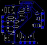
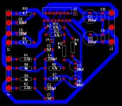
I'm now trying to design the PCB and got somekind of design. All traces are the same width because I didn't know what would be a good size for signal, ground etc.
I managed to pull all the traces but I'm a bit sceptic will this work in practice, so if one of you amazingly helpful experts could give me some advice.
I'll probably need to draw the PCB again, I know
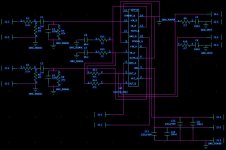
And forgot to mention that I had to change the design software... I'll post the new schematic also.
I'm now trying to design the PCB and got somekind of design. All traces are the same width because I didn't know what would be a good size for signal, ground etc.
I managed to pull all the traces but I'm a bit sceptic will this work in practice, so if one of you amazingly helpful experts could give me some advice.
I'll probably need to draw the PCB again, I know
And forgot to mention that I had to change the design software... I'll post the new schematic also.
Attachments
It's a mess! I know
Need to do a couple of things:
-do some grounding work in the PCB to connect grounds
-make wider power and ground traces
-make right sized decals in some of the caps
and maybe move the speaker terminal next to the chip, so that the output traces can be as wide and short as possible.
How does it sound? Or can you understand anything of my messy sketch?
OK, since no one else has replied I will try to give you some pointers.
1. Power, ground and output tracks need to be alot thicker. At least 50 thou. Somewhere in your CAD package it will be possible to change the track width. Most of the tracks could do with being thicker. 20 thou for low level signal tracks is probably ok.
2. C9 and C10 need to be allot closer to the chip.
3. C11 and C12 should be as close as practical.
4. I would put J2 near the chip amp rather than run the output past the input as this could cause oscillation.
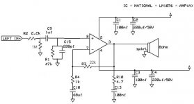
5. You currently have a voltage gain of 48 this is quite high. I would recomend changing the 47K resistor to a 33k or even a 22K part. As the lower gain will reduce the sensitivity of the amplifer reducing noise (hiss) at the ouput. They usually sound a bit better like this as well.
6. I would recomend looking at some of the other PCBs on this forum as it will give you a better idea of how the PCB should look.
Thats it for now.
Regards,
Andrew
1. Power, ground and output tracks need to be alot thicker. At least 50 thou. Somewhere in your CAD package it will be possible to change the track width. Most of the tracks could do with being thicker. 20 thou for low level signal tracks is probably ok.
2. C9 and C10 need to be allot closer to the chip.
3. C11 and C12 should be as close as practical.
4. I would put J2 near the chip amp rather than run the output past the input as this could cause oscillation.
5. You currently have a voltage gain of 48 this is quite high. I would recomend changing the 47K resistor to a 33k or even a 22K part. As the lower gain will reduce the sensitivity of the amplifer reducing noise (hiss) at the ouput. They usually sound a bit better like this as well.
6. I would recomend looking at some of the other PCBs on this forum as it will give you a better idea of how the PCB should look.
Thats it for now.
Regards,
Andrew
Thanks Andrew!
I'll start to draw the new PCB soon.
The smaller hiss would be a good thing, so maybe I'll change R13 and R14 to 22k.
After that I probably will need to change the R7 and R8 also, to match the new values?
And after that some other parts, because R11*C8>=1.4*R7*C1 and R12*C7>=1.4*R8*C2?
Am I right or forgetting something?
Hi!
So is the gain of 23 too small to be used without active preamplifier?
I'm sorry to ask but I'm new in these things
If so, then I'll keep the 47k resistor or will use something smaller, but not as small as 22k.
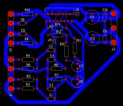
And I've made some changes to the layout also...
So is the gain of 23 too small to be used without active preamplifier?
I'm sorry to ask but I'm new in these things
If so, then I'll keep the 47k resistor or will use something smaller, but not as small as 22k.
And I've made some changes to the layout also...
Attachments
So, do you define the application as "without preamplifier"?
That will be more difficult to voice for hi-fi results, but its possible with LM1875(6) chipamps.
If no preamp, do you have a line level source or do you have a headphone (ipod, computer, etc) source?
Which one?
If you say (define the application) then there's no guessing. Or in my case, "less" guessing.
Hey, it would be really helpful if the PCB had the component values written on it. Then it would be instantly recognisable as to what the components are doing.
Quite impressive school projects you are doing in Finland. Is that just you or is it standard practice?
Here are two things that might be helpful to you.
From http://www.national.com/appinfo/audio/ you can download the Overture Design Guide plus User's Guide. The most important data for your application might be "Heat Sink Size" and "Input for 1% Output". The latter means output power at 1% THD.
You will see that you get unrealistic values for the heat sink with your power supply, if you use 4 Ohm loads. Just to alert you to that fact, because I didn't read anything about the speakers you will be driving, and since you seem to be young, party volumes (=max power) must be expected. If you use 8 Ohm speakers only, you will find a fitting heat sink, though.
The input sensitivity depends of course on the gain. You should try to achieve a value of 775mV, which is the definition of 0dB for general use. The values to use for 4 and 8 Ohm speakers are different however, so you have to decide for a compromise. The original application with Ri=1k and Rf=20k could be just the right solution for you. Maybe a bit more Rf, if your PC/MP3 doesn't give that much output.
From http://www.national.com/mpf/LM/LM4780.html. you can download the datasheet for the LM4780. Page 21 shows a working and tested application. You may wish to copy the input stage. Inspite of everybody's best intentions yours has become a bit messy due to forum dynamics. The National application does the same thing with less parts.
- Status
- This old topic is closed. If you want to reopen this topic, contact a moderator using the "Report Post" button.
- Home
- Amplifiers
- Chip Amps
- Need help with my LM1876 amp-project