Hi all!
I'm about to build an amp using two LM1876. First I was planning to bridge the other amp for sub use to get a 2.1 system, but later I decided to go with two stereo amps; one for speakers and one for subs, total of 4 channels (2.2). Now I'm having a hard time finding a good schematic, because I'm not so much in calculating values for components and the datasheet doesn't give enough information for ME
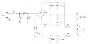
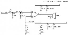
Today I found a amplifier kit with LM1875 from some web site and it had some kind of schematic included. I've understood that the 1876 is a dual version of 1875 so probably I could use the same shematic? I'll attach it with this post so if someone out there would be so kind to look at it and tell their opinion.
Thanks all!
I'm about to build an amp using two LM1876. First I was planning to bridge the other amp for sub use to get a 2.1 system, but later I decided to go with two stereo amps; one for speakers and one for subs, total of 4 channels (2.2). Now I'm having a hard time finding a good schematic, because I'm not so much in calculating values for components and the datasheet doesn't give enough information for ME
Today I found a amplifier kit with LM1875 from some web site and it had some kind of schematic included. I've understood that the 1876 is a dual version of 1875 so probably I could use the same shematic? I'll attach it with this post so if someone out there would be so kind to look at it and tell their opinion.
Thanks all!
Attachments
Much be as much of a secret as your location.some web site
Whilst this amplifer may be stable without a Zobel network I would recomend adding one especially if this is your first design. It is likely to help keep it from oscillating. I just had a look at the LM1876 data sheet and it appears they recomend 4.7R and 100N.
Depending on the cables you connect to the amplifer you may also need the output inductor 0.7uH bypassed with a 10R resistor. (As shown on page 6 of the data sheet). However if your cables are not capacitive (ie you are not using coaxial construction) then you can probably get away without this and amps normally sound better if you can leave this out.
Regards,
Andrew
Hi!
Thanks for your quick answers, they were really helpful.
Some of the component values are different from the schematic, because I got them from the overture design guide -excel sheet.
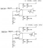
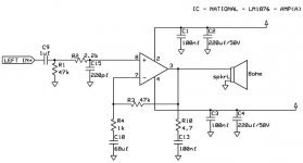
I added the RF-filter to the input and used the values from the guide. If you think it's not good, I can change it to the values you suggested.
Also changed the component names to R1,R2 etc. so it's easier to make changes, and I added the Zobel network. I'm posting only one channel schematic because they're identical...
Thanks for your quick answers, they were really helpful.
Some of the component values are different from the schematic, because I got them from the overture design guide -excel sheet.
I added the RF-filter to the input and used the values from the guide. If you think it's not good, I can change it to the values you suggested.
Also changed the component names to R1,R2 etc. so it's easier to make changes, and I added the Zobel network. I'm posting only one channel schematic because they're identical...
Attachments
Hi,
your new values don't work.
The NFB DC block is 22uF & 2k7. This is ~60mS RC time constant.
The input DC blocking filter must be <=60/1.4 ~40mS.
You have 22uF & 47k giving >1000mS. You must set the input filter narrower than the NFB filter.
The gain is now 120/2.7+1=45times, whereas before it was 19times.
which do you need?
The RF filter is missing. use between 0.5uS and 1.5uS RC time constant.
For 2k2 this requires a parallel cap to ground of between 220nF and 680nF.
Don't mix up the grounds which have the same symbol.
You have a signal ground, a NFB loop ground, a speaker return, a Zobel return, a decoupling ground. These all handle completely different currents and pulses.
Thanks Andrew!
I've made the changes and now it should be ok? I've understood that a gain of about 40 is recommended and would be ok. The previous 19 was a mistake.
I have to get back to that grounding issue when I first get the values correct.
and thanks again!
I've made the changes and now it should be ok? I've understood that a gain of about 40 is recommended and would be ok. The previous 19 was a mistake.
I have to get back to that grounding issue when I first get the values correct.
and thanks again!
Attachments
Hi,
is your source/preamp capable of driving 1k8 (R1) input impedance?
Try reducing C9 to 2u2F and increasing R1 to 18k. You could go even further, all the way to 120k & 330nF. Adopting these values brings R1 much closer in value to R3 (120k) to balance the resistances seen by the two input pins.
C15=220pF
Hello!
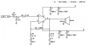
I made some changes again:
-changed R1 to 47k (which I think is quite typical input impedance)
-changed R3 to 47k which is the new value of R1
-changed values of R4 and C10 to match the new R1 and C9 values.
Gain is now 48. The recommended value is 50 so it's good.
I probably forgot something or didn't consider something about these changes to the overall design, so I'm posting it here again for you to see and tell what's wrong
Attachments
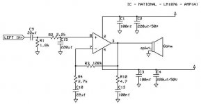
Suggestions:
R4 at 1.1k will probably sound nicer.
Gains up to 45 are generally workable good fidelity with that chip. However, gain of 48 usually results in midfi.
Document C9 as a film cap, because 1uF electrolytics are problematic as input filter caps. --use film cap instead.
Grounds:
Signal ground
Speaker ground (includes zobel)
Power ground
Hello!
I'll have to check what kind of resistors we have in our school. This is a school project so I'm not sure will they order 1,1k resistors just for me, if they don't have it. Or then I'll go and buy it myself.
Next about the grounding, so am I connecting:
power ground: C1,C2,C3 and C4
signal ground: R1, C15 and C10
speaker ground: C13 and SPKR-
?
Nenola said:Hello!
I'll have to check what kind of resistors we have in our school. This is a school project so I'm not sure will they order 1,1k resistors just for me, if they don't have it. Or then I'll go and buy it myself.
Next about the grounding, so am I connecting:
power ground: C1,C2,C3 and C4
signal ground: R1, C15 and C10
speaker ground: C13 and SPKR-
?
That should work just fine.
Suggestion:
Relocate R1 (input load) so that it is the closer to the chip. This will make it parallel with the 220pF. (attach the 47k onto the 220pF, because they, together, are one single filter).
*While 47k is a normal load for audio signal, the 220pF parallel with it drives too-high, non-audio frequencies to ground.
Add 1 megaohm to the input circuit. The location is for the non-loaded side of the input filter cap.
Ah, like this--left to right:
potentiometer or resistor (load), then
2.2k (pass),
1m (load),
0.1uF (pass),
47k || 220pF (load),
LM1876
Ah, that's old language, so "pass" means "in-series," as in carrying an audio signal.
P.S. What voltage and type of transformer are you using?
Nenola said:Hello!
I'm thinking of driving this thing with a +-25 V, so the power supply will be simple: trafo with 2*18V secondaries, bridge rectifier and couple of 10 000uf caps. Will a trafo size of 160VA be enough for two lm1876's? Smaller, bigger?
Oh, that's just fine.
- Status
- This old topic is closed. If you want to reopen this topic, contact a moderator using the "Report Post" button.
- Home
- Amplifiers
- Chip Amps
- Need help with my LM1876 amp-project