I have just made an amp using LM4766T.Made it exactly to the datasheet except I added 1u caps on inputs.Using a sig gen with only one output(1khz 200mv sine) I fed the signal to each input in turn.What happens is this.
1 Input on R,No output from R speaker,no dc,nothing.
2 The L speaker(with no input signal)goes up to full plus supply voltage with heavy ripple,same heavy ripple on plus supply,negative supply is ok.
3 If input signal is applied to L input,same problem occurs on R output.
4 One test sig applied to both inputs,no dc on speaker outputs and no tone output even when test sig. is increased.
The amp is only on for a couple of seconds at a time while I troubleshoot as I know this will fry speakers.LM4766 stays cool all the while.Supply is +/- 32VDC,6800u smoothing caps and transformer are from the dvd player I got the ic's from.
Help!
Attachments
#1 You can't leave the mute pins unconnected.
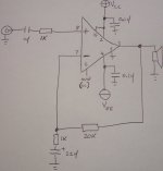
#2 How did you actually build it? Did you make all connections to both A & B channels per the datasheet, or did you follow your hastily drawn sketch? For example, in your drawing, the only connection to the chip's B channel is the Vcc connection on pin 15. If you only connected Vcc and not Vee for the B channel, that would explain your problem.
#2 How did you actually build it? Did you make all connections to both A & B channels per the datasheet, or did you follow your hastily drawn sketch? For example, in your drawing, the only connection to the chip's B channel is the Vcc connection on pin 15. If you only connected Vcc and not Vee for the B channel, that would explain your problem.
I built both channels but drew only one for clarity.Pin 2 and 15 are + supplys for both channels but this ic only has one negative supply pin(pin 4) for both channels.
I will try the mute pin thing but I am sure when I checked the pcb the ic's came from the mute pins (6,11)were just shorted together.
Thanks for your advice guys.
I will try the mute pin thing but I am sure when I checked the pcb the ic's came from the mute pins (6,11)were just shorted together.
Thanks for your advice guys.
when i built my previous one , I was stupid enough to have my +Vcc touch the speaker out pin.
I built it on vero board, and a pin pushed through the isolation of the +vcc wire.
check and double check for shorts everywhere. Especially when you are using veroboard or point to point.
I built it on vero board, and a pin pushed through the isolation of the +vcc wire.
check and double check for shorts everywhere. Especially when you are using veroboard or point to point.
I just checked the datasheet again and this time READ the application notes,not just the diagram.
The diagram shows the mute switch as normally open and I assumed this was un-muted.I was wrong as switch is closed for un-muted operation.Silly me.
Does the input to ground resistor go directly from + input pin to ground or from between input cap and input 1k resistor?
Is the absense of this resistor the reason for unused input making the corresponding output "go high"?
- Status
- This old topic is closed. If you want to reopen this topic, contact a moderator using the "Report Post" button.
- Home
- Amplifiers
- Chip Amps
- + supply volts on my speakers,help!