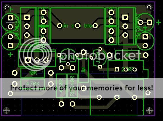
Ozgur, I have corrected the layout of the 337/317 regs. You should adopt the same approach for the LM1083 regs too. ")
An externally hosted image should be here but it was not working when we last tested it.
AndrewT said:Hi Dx,
add the diode protection to the 15V regs.
Add stability caps to the 15V reg pins.
Do you need ~20mA to the LEDs?
Have you tried increasing the adj pin caps above 10uF? Try as high as 220uF.
In fact the leds are for the output stability for LMs.. Because as I read in LMs datasheet they need to source/sink 10mA at least. And as I tested before 78/79 series regulators may being unstable when their outputs are empty.
But, youre right there is no need that 20mA current. So I will reduce their current to 10mA each. With this way I could reduce the temperature of them also (Theyre warming like 50° or so)..
And concerning the adjust pin capacitors of LMs... As also I read in their datasheet, bigger values reduce the high frequency (like 10K or more) PSRR. 10u looks like ideal, but in my current version theyre 2u2 tantaliums (because they were in my drawer)..
However I may replace them after some listening tests..
Thx..
Nuuk said:Ozgur, I have corrected the layout of the 337/317 regs. You should adopt the same approach for the LM1083 regs too.
An externally hosted image should be here but it was not working when we last tested it.
Hmm...
I think I must post my PCB layout also..
Because I have a huge ground plate bottom of my PCB.. So everything is connected to this plate
Why? Because it was simple.
Do you think it causes any bad result?
if one knows how and why a ground plane works then one may be capable of designing a ground plane into a project.
If not, then stick with traces properly routed to minimise interaction between conflicting currents/voltages.
That 240r also draws current. If this is 120r, then it does the whole job of drawing the minimum recommended current for a 337, the 317 is >=5mA.
If not, then stick with traces properly routed to minimise interaction between conflicting currents/voltages.
That 240r also draws current. If this is 120r, then it does the whole job of drawing the minimum recommended current for a 337, the 317 is >=5mA.
Do you think it causes any bad result?
If I remember correctly it is because you shouldn't have current flowing through then R8-C7-C9 connection on the 317 (and R7-C8-C10 on the 337).
ground plane in English, but most would understand ground plate to mean the same thing if the context did not imply a real plate.
My advice:
get rid of the ground plane and design a good star ground that truely separates the various current routes that need separation. eg the zero volt connection from the smoothing capacitors MUST tie in at the output of the reg PCB. Similarly the ground from the high current regs MUST tie in at the output of the low current regs.
Ok
I still have to sort out the bypass for the regulators...
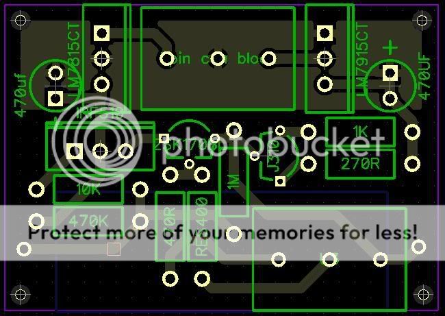
But here is the latest incarnation.
Pedja advised me that I had reversed the J310 and 2Sk170 pins around. It would appear that I had. So I have fixed this in the design. Pedja also advised
"And you may also want to use some pull-down resistor from
2SK170 gate to make sure that it is at the ground voltage, even when potentiometer is not connected."
I figured I would put this in as well
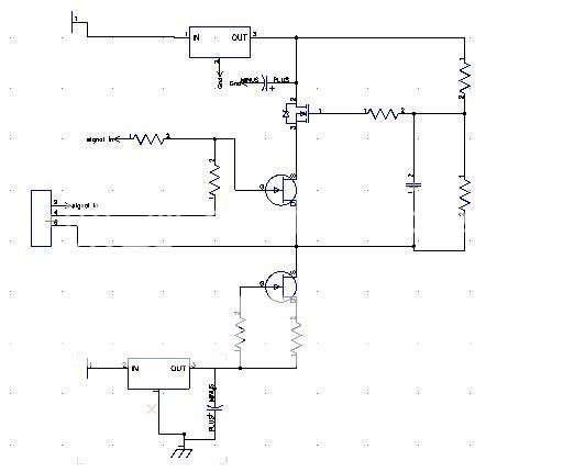
This is the modded schem with the hopefully correct orientation of the J309 and 2Sk170 sorry its messy, not had a lot of time for the detail. The gates, sources and drains are marked on the components.
Just have to choose the components for the bypass caps and add a protection diode for the regs if noone can spot any glaring errors...
Cap wise for the regs ceramic disks are mentioned for the output side, but I am sure that i have read somewhere that larger lytics give better responses in audio... Cant find the article on a search though.
I cant find a recommendation for the input cap type either in the datasheets, only values of 0.22uf or 0.33uf. PET are available in good physical sizes in these values, any good or can anyone suggest better?

Hi.
Plugged into the design a precision trimmer to control the J309. No poblems there.
However I am working on the regulators, and still cant find much info on the bypass caps etc.
Datasheets say 0.33uf before the reg, I was thinking wima mks02 poly's here due to the very small (physical sizes). The only mention that I can find for type here is ceramic disk. But I read plenty about not using ceramics in audio circuits.
For after the reg, datasheets say .1 ceramic to improve transient responce. But in any circuits I see, it seems to be larger lytics that are used.
Shopping around for lytics, the diameters of the caps at 16v values tend to be around the 10-12mm value. However I would appreciate advice on what uf would be appropriate (if lytics are appropriate at all?)
Argh... I can find loads on using lm317's but not on fixed regs
Hi Just,
what does the data sheet say on decoupling the fixed voltage regulator you are planning to use?
Follow it's advice to the letter, at least initially.
After you get it working properly, then you can become more ambitious with experimenting with alternative/additional decoupling.
Some have said that the hi-K ceramics are better (more losses) than the NP0 ceramics for decoupling. MKS also have more losses than MKP, but either of these can only be used initially if the manufacturer specifies them.
Hi Andrew.
Thanks for the reply. I have scoured the datasheets, cant find any mention on what the cap type should be before the reg, just a value .22 or .33uf depending on the manufacturer.
The .1uf value after is described as optional to enhance transient response. I take it you have no issues with putting ceramics into the power lines, I know that some have?
Nuuk said:Blair, I consulted one of my tame gurus and he suggested either 10uF BGN's or Rubycon ZA's either side of the 7805, possibly paralleled with a small film cap of 0.047 uF to 0.1 uF value.
Thanks NUUK. After reading your post I stumbled across a design guide over at National semiconductor which gave similar advice though discussed using larger caps on the output. However with the relatively low current draw on the buffer, I guestimate that your tame guru may be right on the money.
On the ceramic front I learned today that ceramics are bad news for older pre 90's regs, though more modern designs can use them as long as the Datasheet says so.
However I think that using the ZA caps which have a very low esr anyway, bypassed with mini polyester caps at low values and low esr should be very close to using ceramic. I have designed with space for a small polyester, ceramics could be used in the same spot.
I have got the cap traces as close as possible to the regs for the bypass caps. the ZA (small tanks) are just about as close although design wise this is not as crucial.
I'm getting close now to a final design I think. If anyone wishes to pop my bubble, I would rather you did it now. I want to start ordering soon...
BOM
Value.......Type.................Quantity
1uf/200v......Sonicap I....................1
10uf/25v......Rubycon ZA.................4
.22uf/50v.....Wima mks02.................4
................LM7815CT..................1
................LM7915CT..................1
................2SK170BL...................1
................IRF510.......................1
................J310..........................1
1K............MF25 Resistor.............1
470R........MF25 Resistor.............1
10K..........MF25 Resistor.............1
470K........MF25 Resistor.............1
1M...........MF25 Resistor.............1
1K............Precision Var Resistor...1
470R........MF25 Resistor.............1
................3pin con block.............2
- Status
- This old topic is closed. If you want to reopen this topic, contact a moderator using the "Report Post" button.
- Home
- Amplifiers
- Chip Amps
- Pedja Rogic Buffer and component choice for PCB design