Greetings. I've been working on a LM3886 kit from chipamp.com and finally got around to putting things together. Brian's kit is nicely laid out and easy to build, it's been a fun project so far.
I will be using the amp to drive a set of 4 ohm speakers, so I'm trying to keep Vcc near 28v as per the national semiconductor data sheets. To meet this goal I'm using the XFM-D0012 toroid from apex jr which has dual 21.5v secondaries. Surprisingly, when I hooked it up I am getting ~27v AC per secondary, which leads to a rectified +/- 35v output from the power supply.
Is something up here? I can think of three possibilities:
1. I hooked up the toroid wrong.
2. My calculations were wrong. I was assuming 21.5v x 1.4 = ~30V rails.
3. The toroid is putting out a higher voltage than it should (27v vs 21.5v).
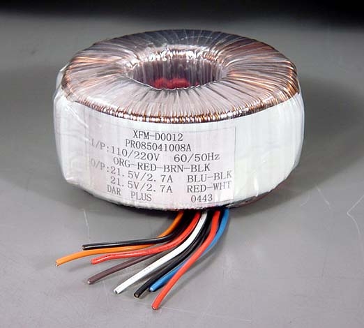
There were no instructions for the toroid, so I'm hoping someone can review my wiring scheme. Here's a picture of the toroid.
Here's how I have it hooked up and also an explanation of my assumptions. This is for 120v mains. I'm running dual-mono power supplies with a separate toroid and ps board per amp.
I measured ~12 ohms between orange/red and also between brown/black, my assumption is that each pair is one primary. For 120v I need them in parallel so I hooked up orange to brown and red to black this results in an input resistance of ~6ohms which seemed reasonable. I'm also assuming that the colors are listed in order of winding so that orange->red is in phase with brown->black.
With the above wiring I measure 27v on each of the outputs (blue/black and red/white). I've wired blue to AC1 (line above), black to AC1 (no line), red to AC2 (line
above), and white to AC2 (no line).
Here is a schematic of the ps circuit:
Can anybody verify that the above wiring is correct?
When powered up the blue LEDs light up and the amp seems to work properly, my main concern is the high rail voltages since I will be using a 4 ohm load.
During lower power usage the heat sink did not get above 100 degrees F (ambient temp around 65). I was using my laptop CD drive as a test source, and at one point the computer went to sleep and when I woke it up the lightbulb in series with the amp glowed brightly, there was a strange humming in the speaker, and the chip temperature spiked from 90 deg F to 100 deg F. Any idea what could cause this?
Any input or suggestions is greatly appreciated. I've been building speakers for years, but this is my first amp project and it's been quite fun.
Here are some pictures:
more here
- Matt
I will be using the amp to drive a set of 4 ohm speakers, so I'm trying to keep Vcc near 28v as per the national semiconductor data sheets. To meet this goal I'm using the XFM-D0012 toroid from apex jr which has dual 21.5v secondaries. Surprisingly, when I hooked it up I am getting ~27v AC per secondary, which leads to a rectified +/- 35v output from the power supply.
Is something up here? I can think of three possibilities:
1. I hooked up the toroid wrong.
2. My calculations were wrong. I was assuming 21.5v x 1.4 = ~30V rails.
3. The toroid is putting out a higher voltage than it should (27v vs 21.5v).
There were no instructions for the toroid, so I'm hoping someone can review my wiring scheme. Here's a picture of the toroid.
Here's how I have it hooked up and also an explanation of my assumptions. This is for 120v mains. I'm running dual-mono power supplies with a separate toroid and ps board per amp.
I measured ~12 ohms between orange/red and also between brown/black, my assumption is that each pair is one primary. For 120v I need them in parallel so I hooked up orange to brown and red to black this results in an input resistance of ~6ohms which seemed reasonable. I'm also assuming that the colors are listed in order of winding so that orange->red is in phase with brown->black.
With the above wiring I measure 27v on each of the outputs (blue/black and red/white). I've wired blue to AC1 (line above), black to AC1 (no line), red to AC2 (line
above), and white to AC2 (no line).
Here is a schematic of the ps circuit:
An externally hosted image should be here but it was not working when we last tested it.
Can anybody verify that the above wiring is correct?
When powered up the blue LEDs light up and the amp seems to work properly, my main concern is the high rail voltages since I will be using a 4 ohm load.
During lower power usage the heat sink did not get above 100 degrees F (ambient temp around 65). I was using my laptop CD drive as a test source, and at one point the computer went to sleep and when I woke it up the lightbulb in series with the amp glowed brightly, there was a strange humming in the speaker, and the chip temperature spiked from 90 deg F to 100 deg F. Any idea what could cause this?
Any input or suggestions is greatly appreciated. I've been building speakers for years, but this is my first amp project and it's been quite fun.
Here are some pictures:
more here
- Matt
TWO HIGH
Your AC lines can very greatly from place to place and time to time. Ive had AC mains drop as low as 102VAC and go as high as 127VAC. Check your mains, if your trans primary is 110VAC and your mains are high like 120+VAC there is your difference.
Thats why most manufactures allot for +/-20% mains variance.
Your chip will work with a 4Ohm load at +/-30DC just make sure you have adequate heat sinks.
Re: TWO HIGH
The transformer label shows a 110/220V primary winding, so tiltedhalo's comment is right on the money. The voltage will also be a bit higher because the transformer is not being loaded down.
tiltedhalo said:Check your mains, if your trans primary is 110VAC and your mains are high like 120+VAC there is your difference.
The transformer label shows a 110/220V primary winding, so tiltedhalo's comment is right on the money. The voltage will also be a bit higher because the transformer is not being loaded down.
Thank you for all the helpful replies, that's why this place is such a great forum
I'll measure the AC at the house tonight to see how close it is to 120v. I'll also measure the dc voltages under load to see what they are. The good news is that I only have ~100mV off offset without the feedback capacitor and just a little hissing noise from the speakers. Everything is good so far. I'm looking forward to finishing the second amp so I can test everything in stereo.
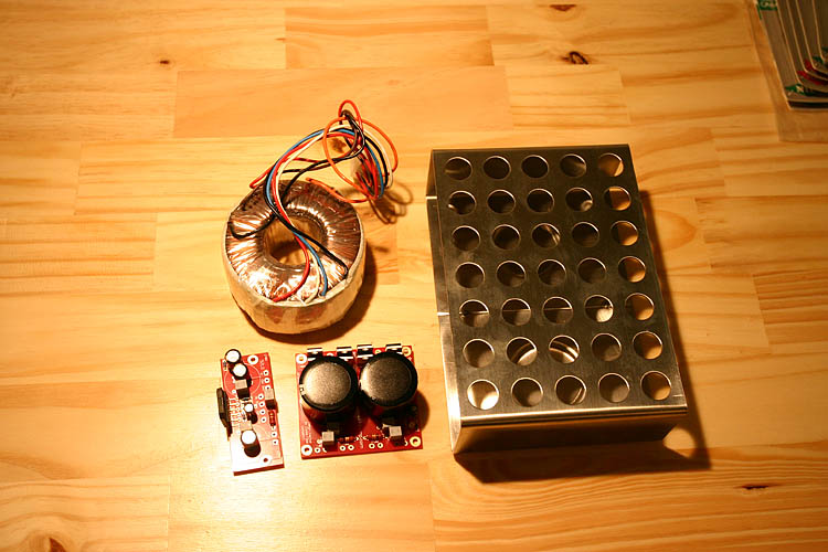
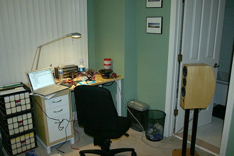
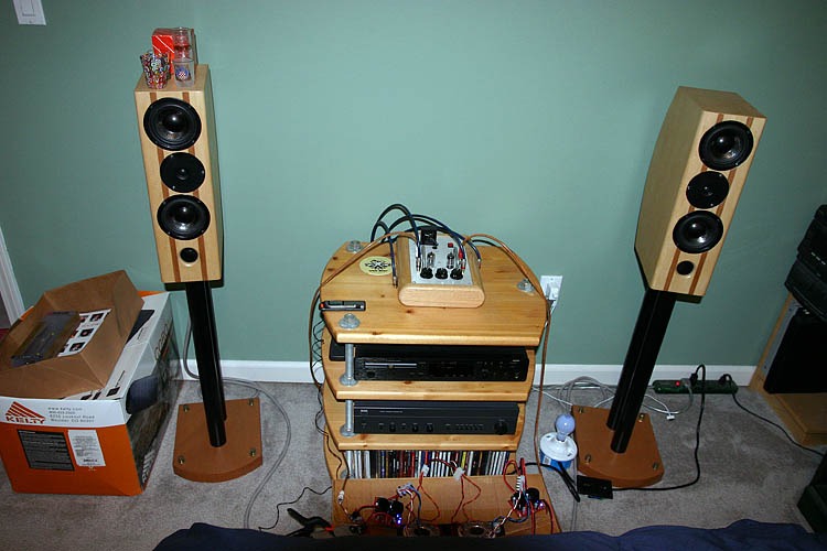
The "big" problem is that I'm not sure I'm going to be able to fit everything into the enclosures I want to use. My goal is to build two mono-blocks, but I may wind up with two ps units and a single amp unit, or possibly two ps units and two amp units. It seems a bit silly to go with a four enclosure fully separated solution for a lower cost amp like this. The enclosures are going to be the Ikea plate warmers shown in the picture with some metal grid below the top holes and solid maple sides.
danielwritesbac,
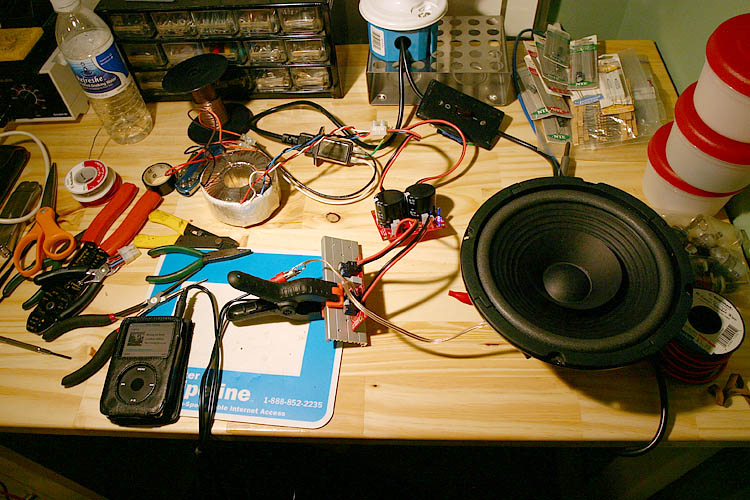
The speaker on the desk is indeed a B20, there's a more "up close" photo in the additional photos I linked to. Nelson Pass was very generously giving them away at Burning Amp. At some point I'm going to put them in a set of Curvy Chang enclosures.
- Matt
I'll measure the AC at the house tonight to see how close it is to 120v. I'll also measure the dc voltages under load to see what they are. The good news is that I only have ~100mV off offset without the feedback capacitor and just a little hissing noise from the speakers. Everything is good so far. I'm looking forward to finishing the second amp so I can test everything in stereo.
The "big" problem is that I'm not sure I'm going to be able to fit everything into the enclosures I want to use. My goal is to build two mono-blocks, but I may wind up with two ps units and a single amp unit, or possibly two ps units and two amp units. It seems a bit silly to go with a four enclosure fully separated solution for a lower cost amp like this. The enclosures are going to be the Ikea plate warmers shown in the picture with some metal grid below the top holes and solid maple sides.
danielwritesbac,
The speaker on the desk is indeed a B20, there's a more "up close" photo in the additional photos I linked to. Nelson Pass was very generously giving them away at Burning Amp. At some point I'm going to put them in a set of Curvy Chang enclosures.
- Matt
Did the label on that transformer really say 2.7 amps?
If so, that's for monoblocks, but sure you can put the transformer in the enclosure--just don't run the signal cables across it.")
Ah, be sure to duplicate test bench conditions within the enclosure. This is regarding the ground lines. There's not just one. The speaker ground goes nowhere but the speaker. . . the input ground goes nowhere but the input. . . the CG common ground goes to the enclosure.
So, how does it sound? OH! I mean, how does it sound on the loudspeaker? We don't really want to make the B20 driver go hopping around all over the desk.
EDIT: That transformer can run stereo lm3886 if using the configuration suggested by chipamp.com.
Bit of Artic Ceramique thermal paste to heatsink it and it'll do fine.
EDIT: The grounding is something to watch on stereo config. Each individual speaker ground goes to its own speaker terminal.
Each individual signal ground goes only to the input--those wires are exactly the same length for the stereo pair.
The power lines are exactly the same length for the stereo pair.
The CG's, common grounds are exactly the same length for the stereo pair.
This and some luck will avoid a ground loop.
If so, that's for monoblocks, but sure you can put the transformer in the enclosure--just don't run the signal cables across it.
Ah, be sure to duplicate test bench conditions within the enclosure. This is regarding the ground lines. There's not just one. The speaker ground goes nowhere but the speaker. . . the input ground goes nowhere but the input. . . the CG common ground goes to the enclosure.
So, how does it sound? OH! I mean, how does it sound on the loudspeaker? We don't really want to make the B20 driver go hopping around all over the desk.
EDIT: That transformer can run stereo lm3886 if using the configuration suggested by chipamp.com.
Bit of Artic Ceramique thermal paste to heatsink it and it'll do fine.
EDIT: The grounding is something to watch on stereo config. Each individual speaker ground goes to its own speaker terminal.
Each individual signal ground goes only to the input--those wires are exactly the same length for the stereo pair.
The power lines are exactly the same length for the stereo pair.
The CG's, common grounds are exactly the same length for the stereo pair.
This and some luck will avoid a ground loop.
The amps are wired and playing music (Dire Straits) as I write this. Here's a photo of the test setup:
Source: Marantz DR 6000
Preamp: Bottlehead Foreplay w/ Anticipation Upgrade
Speakers: Adire Audio GrandPop! (4ohm)
Measurements: (channel A/channel B)
Wall voltage: 121.5v
Secondaries (no load): 26.9v/26.9v
Secondaries (load): 26.6v/26.6v
Rails (no load): 36.8v/36.8v
Rails (load) 35.3v/35.4v
DC Offset: 106mv/105mv
The chips are on undersized heatsinks and not yet mounted using any compound, the heatsinks are running ~101 deg F while playing at a low volume.
I was hoping for rails around 30v and wound up with 35v rails, so I'm a little concerned about issues with a 4 ohm load. Hopefully decent heatsinks will solve that issue. Is there anything I should watch out for as an indicate of amplifier distress?
The transformers put out 2.7A. Based on the equations at National Semiconductor I estimated the power requirements for 68w@4ohm to be 23.3v @ 5.8A and for 38w@8ohm they would be 24.7v @ 3.1A. I figured dual 2.7A transformers should be enough.
With no input connected I hear a slight hiss in each speaker from a distance of ~3". There is no hum, which surprises me since the amps are currently not in an enclosure and sitting on a cardboard box. Grounding is all handled through the board connections, I'll use a similar scheme in the enclosure but will of course make sure the chassis is safety grounded.
I did notice a slight AM radio pickup on the left channel, which I attribute to the complete lack of shielding of the circuit boards and the input lines.
My preamp has a 60Hz hum that I am in the process of tracking down. With my normal amp (amp section of a NAD 314) this is annoying but not too big of a deal. The chipamp has considerably more gain and the hum is very noticeable, I'll have to work on debugging the preamp soon. Another issue is that the tube preamp puts out a lot of voltage on the outputs, when coupled with the high gain of the LM3886 this means the usable range of the volume pots is about 1/4 turn. I might consider padding the input of the chipamp to compensate.
Ok, so enough technical business, how do they sound? (caveats: no enclosure, wired through ancient and corroded rca jacks, still using a 60w lightbulb as a fuse)
So far I am impressed. I'm not sure if I'm ready to say they sound much better than the NAD, but I haven't had a chance to turn up the volume yet. Imaging and "space" around instruments are very impressive. The sound is very clean, though I'm worried that the treble might be a little bit too thin since cymbals don't have a lot of ring or air to the sound. I'll have a much more detailed review tomorrow when I can turn up the volume a bit.
Thanks again for everyone's input and advice.
- Matt
Source: Marantz DR 6000
Preamp: Bottlehead Foreplay w/ Anticipation Upgrade
Speakers: Adire Audio GrandPop! (4ohm)
Measurements: (channel A/channel B)
Wall voltage: 121.5v
Secondaries (no load): 26.9v/26.9v
Secondaries (load): 26.6v/26.6v
Rails (no load): 36.8v/36.8v
Rails (load) 35.3v/35.4v
DC Offset: 106mv/105mv
The chips are on undersized heatsinks and not yet mounted using any compound, the heatsinks are running ~101 deg F while playing at a low volume.
I was hoping for rails around 30v and wound up with 35v rails, so I'm a little concerned about issues with a 4 ohm load. Hopefully decent heatsinks will solve that issue. Is there anything I should watch out for as an indicate of amplifier distress?
The transformers put out 2.7A. Based on the equations at National Semiconductor I estimated the power requirements for 68w@4ohm to be 23.3v @ 5.8A and for 38w@8ohm they would be 24.7v @ 3.1A. I figured dual 2.7A transformers should be enough.
With no input connected I hear a slight hiss in each speaker from a distance of ~3". There is no hum, which surprises me since the amps are currently not in an enclosure and sitting on a cardboard box. Grounding is all handled through the board connections, I'll use a similar scheme in the enclosure but will of course make sure the chassis is safety grounded.
I did notice a slight AM radio pickup on the left channel, which I attribute to the complete lack of shielding of the circuit boards and the input lines.
My preamp has a 60Hz hum that I am in the process of tracking down. With my normal amp (amp section of a NAD 314) this is annoying but not too big of a deal. The chipamp has considerably more gain and the hum is very noticeable, I'll have to work on debugging the preamp soon. Another issue is that the tube preamp puts out a lot of voltage on the outputs, when coupled with the high gain of the LM3886 this means the usable range of the volume pots is about 1/4 turn. I might consider padding the input of the chipamp to compensate.
Ok, so enough technical business, how do they sound?
(caveats: no enclosure, wired through ancient and corroded rca jacks, still using a 60w lightbulb as a fuse)So far I am impressed. I'm not sure if I'm ready to say they sound much better than the NAD, but I haven't had a chance to turn up the volume yet. Imaging and "space" around instruments are very impressive. The sound is very clean, though I'm worried that the treble might be a little bit too thin since cymbals don't have a lot of ring or air to the sound. I'll have a much more detailed review tomorrow when I can turn up the volume a bit.
Thanks again for everyone's input and advice.
- Matt
SOUNDS GOOD?
Just make sure your heat sinks are large enough for the load and voltage, take a look at nationals figures for dissipation and heat sinking.
I have tested the 3886 and 3875, I prefer the 3875 at +/-75VDC at low outputs with success, the little buggers get red hot but did not go into spike protection. Remember these chip are totally built on a very small die, thermal management is nationals biggest concern with supply voltage hence the low max supply not the transistors ability to handle it, but keep the dissipation down to a level that can be shed.
As for the sound, give it some time, they do need to burn in a bit. The treble will mellow out with time, if not try adding a 10uf silmic bypassed with a 1, .1 uf film and foil cap at the input.
Re: schematic question
The layout had me bluffed for hours until I finally marked a stripe on the diodes (marker that writes on plastic).
Then it made sense.
This preamp discussion and the results are really fascinating to me. Folks have been reporting amazing results when using a preamp, and those that don't have been reporting a lack of bass. I guess you've got more bass than anyone.
jb74 said:I have some of the chipamp.com boards and the manual with that
power supply schematic as shown in post 1.
I wonder if the boards are marked and connected correctly but
are different from that specific drawing [see bottom 4 diodes]
The layout had me bluffed for hours until I finally marked a stripe on the diodes (marker that writes on plastic).
Then it made sense.
slomatt said:I opened up the preamp today to try to fix the hum issue, and somehow resulted with more hum that I started with. Arg. I must have introduced a cold solder joint on a ground wire somewhere.
- Matt
This preamp discussion and the results are really fascinating to me. Folks have been reporting amazing results when using a preamp, and those that don't have been reporting a lack of bass. I guess you've got more bass than anyone.
Just ran across this looking up the transformer you happened to use...
A quick guess-- the input to the amp is DC coupled (default chipamp kit setup), the computer went to sleep and the audio input floated off to a very large DC offset, which the amp faithfully multiplied and output... The lightbulb would go on because the 3886 would be sinking all the power it could get, and the speaker would be humming because the combo lightbulb tester / current sink would mean lots and lots of ripple on the rectifier supply output...
Monty
slomatt said:During lower power usage the heat sink did not get above 100 degrees F (ambient temp around 65). I was using my laptop CD drive as a test source, and at one point the computer went to sleep and when I woke it up the lightbulb in series with the amp glowed brightly, there was a strange humming in the speaker, and the chip temperature spiked from 90 deg F to 100 deg F. Any idea what could cause this?
A quick guess-- the input to the amp is DC coupled (default chipamp kit setup), the computer went to sleep and the audio input floated off to a very large DC offset, which the amp faithfully multiplied and output... The lightbulb would go on because the 3886 would be sinking all the power it could get, and the speaker would be humming because the combo lightbulb tester / current sink would mean lots and lots of ripple on the rectifier supply output...
Monty
power supply..............error ?
Is the bridge rectifier connection correct on your power supply diagram ?I am unable to copy that picture here.
but here is the doubt.
On the lower bridge ( AC2) the diodes seeem to be reversed !The capacitors following it are properly oriented but the diodes are all wrong. Plus output goes to -ve of the cap and minus from rectifier goes to + of the cap !
All four diodes in this section (AC2) probably need to be reversed to correct the problem.
Can someone confirm this please.
Maybe the board is Ok ?
slomatt said:The chips are on undersized heatsinks and not yet mounted using any compound, the heatsinks are running ~101 deg F while playing at a low volume.
I was hoping for rails around 30v and wound up with 35v rails, so I'm a little concerned about issues with a 4 ohm load. Hopefully decent heatsinks will solve that issue. Is there anything I should watch out for as an indicate of amplifier distress?
With no input connected I hear a slight hiss in each speaker from a distance of ~3". . .
. . . The chipamp has considerably more gain and the [preamp] hum is very noticeable, I'll have to work on debugging the preamp soon. . . Another issue is that the tube preamp puts out a lot of voltage on the outputs, when coupled with the high gain of the LM3886 this means the usable range of the volume pots is about 1/4 turn. I might consider padding the input of the chipamp to compensate.
Hi Matt! Those speakers are gorgeous!
101F is an excellent temperature for those amps, indicating good health.
For 4 ohm loads with 35vdc rails--its just fine on more generous heatsinks. That's a nice voltage to use because it helps prevent clipping (in comparison to 30vdc rails). So, its good.
Please do check the temperature of the power supply caps, as their temp indicates the health of the power supply.
For a little gain-drop along with a little less DC, replace the 1k at the input with 2.2k, but save that 1k for the next step.
Next, recycle that 1k instead of 680R at the NFB. Specifically, that's using the 1k in the NFB instead of the 680R. That will drop the gain sufficiently for use with a preamp.
With no input connected. . . Okay, if the amplifier doesn't have a potentiometer, you can use a plain resistor as an additional load. This additional resistor would go, from signal, to signal ground at the amplifier input signal connections. Usual values here are 20k, 22k, 33k, 50k, 56k, 100k, and any of those should stop that little noise.
An extra, precautionary measure, is to measure the DC offset while the preamp is connected, but outputting no signal. That will identify if your preamp contains a DC blocker or if you need to add one. The measurments would be "slightly" higher, but not a huge figure, if there's already sufficient protection.
ashok -
Re: power supply..............error ?
I think that you are correct (see my post 11 in this thread)
If the Power supply board connections in the LM3886 kits from chipamp.com were in fact identical to that schematic drawing in post 1,
it would surely have been discovered long ago.
Re: power supply..............error ?
I think that you are correct (see my post 11 in this thread)
If the Power supply board connections in the LM3886 kits from chipamp.com were in fact identical to that schematic drawing in post 1,
it would surely have been discovered long ago.
It made no sense to me either. But, I thought it was just me, so I tossed the diagram out. Next, after fetching the textbook, pencil, and sketchpad, I found that the power supply circuit board itself. . . is just fine.
The power supply circuit board is a great visual bluff because of its 90 degree layout, with the grounds going down the center like an amplifier instead of down the outside edges like a standardized power supply.
Its performance is sublime--very clean power.
However, "updating" the original amplifier board layout to remove the 1000uF (sometimes 1500uF) caps and replace them with downsized 100uF caps, makes, in my opinion, an "questionably unnecessary difference" in the amplifier's sonic signature (I hear an obnoxious upper-midrange). In my own case, I will be rebuilding my amplifiers back to the original standard; however, I do still intend to use the really good power supply board, and perhaps purchase more for other projects.
- Status
- This old topic is closed. If you want to reopen this topic, contact a moderator using the "Report Post" button.
- Home
- Amplifiers
- Chip Amps
- Toroid question and LM3886 photos