While working on chip amps based on the LME49810 i had the idea to use an LM4562 to drive a discrete output stage instead of the usual driver ic's.
Once finished my first prototype i'm really impressed by the results, so i have to share the schematic with you.
http://www.telefonica.net/web/escapades/AMPL.mdi
This can be used in two ways: 12W (8 Ohm) class A and 50/100W (8/4 Ohm) class AB bridging two of them.
Notes:
Input cap is ommited since the use of a the inverting part when bridged results in very low input impedance and decoupling must be applied before the buffer. The use of a dc servo is recommended.
Transistor choice is based only on what I have on hand. Replacing with better parts will yeld to better sound.
Bias is class AB and can be changed using the vbe multipliers. The idea is to choose the desired bias current and set it modifying the vbe multipliers to get 0V output with 0V input to allow a better use of the LM4562 output swing.
The schematic ommits decoupling capacitors. Use 2200 uf paralleled with 0.22/1uF polypropylene in current sources, output stage and LM4562 voltage input. Good regulation at LM4562 will give better sound than unregulated/78XX power. Output stage must be unregulated.
Higher current at bias stage will help to get better slew rate at the expense of higher power consumption and heat dissipation. Slew rate at the output stage MUST be higher than slew rate of the opamp to ensure stability.
Current sources at bias stage may be deliverately imbalanced to bias the LM4562 into class A. This can make the driver opamp to always sink or always source depending on what sounds the best
but i havn't done any listening tests. Biasing the opamp into class A will reduce the output swing and it must be done in a way the ompamp is always capable to give enough current to ensure proper slew rate. Calculation is easy and can be done using load impedance and output transistor transconductance and gate capacitance.
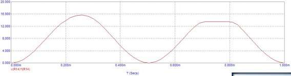
The bridged setup should have a 40V/usec slew rate that is fast enough for a 50W/100W amplifier.
Changing the output transistors requires reducing bias voltage since the IRFP ones have really high threshold voltage. Replacing them without altering Vbe multipliers may lead to a deep class A bias that probably will end up with the output stage.
Putting Vbe multipliers in the same heatsink than the output stage will help to give some thermal compensation for transistors that need it (IRFP do really need it). Thermal compensation will not be optimal since MOSFET transistors have different thermal behaviour than BJT ones. It's recommended to choose a largue heatsink and use transistors that do not need to be thermally compensated.
Using a cap in parallel with GS of the lower input capacitance is recommended to help reducing asymetric distortion.
Enjoy bulding it!
Once finished my first prototype i'm really impressed by the results, so i have to share the schematic with you.
http://www.telefonica.net/web/escapades/AMPL.mdi
This can be used in two ways: 12W (8 Ohm) class A and 50/100W (8/4 Ohm) class AB bridging two of them.
Notes:
Input cap is ommited since the use of a the inverting part when bridged results in very low input impedance and decoupling must be applied before the buffer. The use of a dc servo is recommended.
Transistor choice is based only on what I have on hand. Replacing with better parts will yeld to better sound.
Bias is class AB and can be changed using the vbe multipliers. The idea is to choose the desired bias current and set it modifying the vbe multipliers to get 0V output with 0V input to allow a better use of the LM4562 output swing.
The schematic ommits decoupling capacitors. Use 2200 uf paralleled with 0.22/1uF polypropylene in current sources, output stage and LM4562 voltage input. Good regulation at LM4562 will give better sound than unregulated/78XX power. Output stage must be unregulated.
Higher current at bias stage will help to get better slew rate at the expense of higher power consumption and heat dissipation. Slew rate at the output stage MUST be higher than slew rate of the opamp to ensure stability.
Current sources at bias stage may be deliverately imbalanced to bias the LM4562 into class A. This can make the driver opamp to always sink or always source depending on what sounds the best
but i havn't done any listening tests. Biasing the opamp into class A will reduce the output swing and it must be done in a way the ompamp is always capable to give enough current to ensure proper slew rate. Calculation is easy and can be done using load impedance and output transistor transconductance and gate capacitance.
The bridged setup should have a 40V/usec slew rate that is fast enough for a 50W/100W amplifier.
Changing the output transistors requires reducing bias voltage since the IRFP ones have really high threshold voltage. Replacing them without altering Vbe multipliers may lead to a deep class A bias that probably will end up with the output stage.
Putting Vbe multipliers in the same heatsink than the output stage will help to give some thermal compensation for transistors that need it (IRFP do really need it). Thermal compensation will not be optimal since MOSFET transistors have different thermal behaviour than BJT ones. It's recommended to choose a largue heatsink and use transistors that do not need to be thermally compensated.
Using a cap in parallel with GS of the lower input capacitance is recommended to help reducing asymetric distortion.
Enjoy bulding it!
Attachments
")
Sorry guys, i've noticed the schematic misses the 470 Ohms resistors at the gate of the mosfet [Corrected] . Building it without them will lead to catastrophic results.
I've built mine on veroboard in less than an hour and i'm really impressed with the results.
Thanks for exporting it to pdf. I have no pdf printer so i had to use a less common format.
I've built mine on veroboard in less than an hour and i'm really impressed with the results.
Thanks for exporting it to pdf. I have no pdf printer so i had to use a less common format.
ionomolo said:Sorry guys, i've noticed the schematic misses the 470 Ohms resistors at the gate of the mosfet [Corrected] .
Thanks for exporting it to pdf. I have no pdf printer so i had to use a less common format.
Here it is:
Attachments
I use Vbe multipliers because they allow to set the bias voltage easier using a trimpot or changing resistor values. Using Leds would confine the amp to a reduced set of transistors if i do a board.
One of the main features of this amp, among ease, is the fact that you can roll both output transistors and driver opamp.
There is any reason other than reducing parts count not to use the vbe multiplier?
Has somebody built one?
One of the main features of this amp, among ease, is the fact that you can roll both output transistors and driver opamp.
There is any reason other than reducing parts count not to use the vbe multiplier?
Has somebody built one?
ionomolo said:There is any reason other than reducing parts count not to use the vbe multiplier
Hi ionmolo. I'm not saying that a diode string is better than a Vbe multiplier, just that it is worth trying out. Different combinations/colors of LEDs can give you different bias voltages, but as you said they wouldn't be as adjustable as the multiplier.
You could even try a combination of diodes and resistors for a bit more adjustability over just diodes.
I will give it a try tomorrow. One thing that really favours LM4562 in front of dedicated drivers is that you can try your schematics in protoboard before building a soldered prototype.
Now it's really cold here and this thing sounds better. It may seem a very subjectivistic approach but bias current is cut in half (170 mA vs 80). I think that gm doubling distortion is worse with these mosfets than pure crossover.
Merry Christmas!
Now it's really cold here and this thing sounds better. It may seem a very subjectivistic approach but bias current is cut in half (170 mA vs 80). I think that gm doubling distortion is worse with these mosfets than pure crossover.
Merry Christmas!
There's also a thing that bothers me about the LM4562. When I push it, say above 1 or 2 Vrms the sound changes dramatically from warm to extremely analytical.
I don't know if it changes to better or worse but it's easy noticeable. Looking at the distortion plots from the datasheet it seems it behaves better when pushed, but i'm not enthusiastic about the clinical sound of it at high volumes and having a volume point where the sound changes it's coloration it's quite annoying.
Somebody has experimented with it? (It also affects headphone amplifiers and other things i've done with this ic)
Thanks
I've been using the LM4562 as a differential buffer for an LM3875 and I did notice that it changed character when upping the supply voltage from +/-15V to +/-18V and also when changing the gain from 1 to 2. I believe I preferred the +/-18V supplies combined with a gain of 2. I seem to prefer a more analytical sound that lets all the little details of the recording through.
ionomolo said:There's also a thing that bothers me about the LM4562. When I push it, say above 1 or 2 Vrms the sound changes dramatically from warm to extremely analytical.
Thanks
It is because the circuit clips non-symmetrically, what you are hearing is odd order harmonics which sounds clinical, and cold.
Nico
Attachments
Thanks, i'm using non-symmetrical supplies (17-18.5). I'll work a bit arround it. I also prefer analytical sound since it's much easier to color the sound in the preamp stage (Yeah, tubes). I like the word gainclone because I want a chipamp that clones the signal with gain : ). But what i feel from the LM4562 is some sort of ultrasonic fog that surrounds everything and this might not be a clean sound but rather an IM product.
This afternoon I'll bias it into class A to see what happens. I will also try to keep both supplies as matched as possible.
I also don't like the sound of the LM4562 at unity gain.
Thanks
This afternoon I'll bias it into class A to see what happens. I will also try to keep both supplies as matched as possible.
I also don't like the sound of the LM4562 at unity gain.
Thanks
- Status
- This old topic is closed. If you want to reopen this topic, contact a moderator using the "Report Post" button.
- Home
- Amplifiers
- Chip Amps
- my new amplifier (beta version)