Hi okapi,
For unbalanced to balanced conversion, I also like the circuit shown in Figure 6-54, in Walt Jung's "Op Amp Applications Handbook" (as long as it is driving balanced high impedances).
Chapter Six can be downloaded by right-clicking on the URL below and selecting "Save Target As".
Chapter 6 (3289 kB):
http://www.analog.com/library/analogDialogue/archives/39-05/Web_Ch6_final_I.pdf
Figure 6-54 is on page 67 of the PDF file, and is labeled as Page 6.65.
As he says in the accompanying text, if you use an eight-resistor 20k film-resistor array, the circuit can be built with only eight components. And note that the OP275 dual opamp can run on up to +/-22V.
The circuit is a simple "Inverter Follower" differential line driver. But it has some very nice performance features, especially considering its low cost and low complexity.
You should probably also look at the circuit in Figure 6-56, on page 69 of the PDF file. You could either build something similar with discrete parts (with tightly-matched resistors), or just use the Analog Devices SSM2142 (or something similar).
Returning to Okapi's original question, there is also a simple and cheap (and good) all-in-one solution.
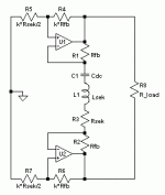
One can combine the balancing with the bridging, using the copper-compensated zero-field topology (simplifed schematic is attached). This allows for small and affordable xfomers, like the small Neutrik or Lundahl types, but even a $5 model might easily suffice for a chip-amp performance level. Only thing which would be not on top level is CMRR, but this can be significantly compensated for with an arrangement of two equal xformers in anti-parallel/anti-series.
I've done this circuit with small-signal op-amps with success, it should work equally well with any power op-amp, given proper compensation for stability if required (e.g., a series-RC accross the xformer might be needed to get a stable HF gain for a decompensated op-amp). The op-amps run in inverting mode with only little common-mode voltage on their inputs which helps linearity. Also impedances can be very low. As in every true bridge, GND is only a reference voltage (Vs/2) and does not carry load current, therefore a single supply can be used and the ref. voltage can come from a simple divider. The divider can by bypassed to the supply end with lower supply rejection from the chips, which is the neg rail for LM3886 IIRC. The series cap after the xfomer is neccesary to keep DC away from the xformer and it gives unity gain for DC which keeps output offset low.
But if you want to go for a single IC symmetrizer, consider the THAT 1600 series. Those will need a buffer in front of them, as will the SSM counterpart. However, the simplest/cheapest circuit would still be a buffer, followed by an inverter.
Note: Forget about the high CMRR of the IL300... not true (saw the CMRR vs. freq. graph too late...)
- Klaus
Attachments
thanks to everyone for their replies and sorry i let this thread lie dormant for so long. the first week back was a busy one.
i am still integrating a couple of the posts 10 21 22
but it is obvious my question needs some clarification at this point.
immediately i have some assembled lm4780 chip amps running in parallel that i would like to create a balanced signal for so that i can bridge them. i am interested in seeing what advantages more power will bring to my system (if i can reduce CMRR at the same time, great). depending on how this works, i may then build a bridge parallel chip amp using LM3875 chips (6 chips/chan, two groups of three running in parallel).
i may now alter this plan and begin experimenting with some of the different methods proposed in this thread for balancing a signal and use only two chips. i expect this should help me with the posts i don't fully appreciate and lead to more questions.
thanks again.
preliminary summary conclusions
positives and negatives for creating balanced signal from transformers and SS devices
transformer
+ high CMRR
+ simplicity, no other components
+ increases the input impedance of the amp??
- cost, this can be offset by using a cheaper transformer in a zero field topology but this requires the amps be used in inverted mode??
Op Amp or SS solution
+ low cost
+ good CMRR performance although maybe not quite as good as the best transformers??
- the devices tend to have a low input impedance and require a buffer (ex THAT 1600 series)??
- complexity, devices require a power supply and OP Amp designs require more parts (not necessarily the case for SS solutions like the DRV134 that needs only three parts including itself).
are there performance measures in which the SS solutions outperform transformers?
corrections and comments are welcome especially on the double ?? sections.
related question. what is the best position for the balancing device? near the amp or the source?
hi all
I have a Aikido 12Vac line preamplifier before the 2 x IcePower 125ASX2, Since I am using icepower in BTL mode, I need unbalanced to balanced conversion from preamp output to the power amp input.
SO I bought a 600:10K Audio Transfromer, my plan is tto take unbalanced (RCA) output and turn it into balanced XLR output and insert into the icepower amplifier.
The question is; Which side of the audio transformer should be unbalanced, should I use the 10K side as unlbalanced input, and take the 600 ohm side as output, to the balanced xlr input of the power amplifier? or should I do it vice versa?
????
You want the same impedance on both sides. I suggest 10K:10KCT.
Hi
Why 10K:10K instead of 600:600?
hi all
I have a Aikido 12Vac line preamplifier before the 2 x IcePower 125ASX2, Since I am using icepower in BTL mode, I need unbalanced to balanced conversion from preamp output to the power amp input.
SO I bought a 600:10K Audio Transfromer, my plan is tto take unbalanced (RCA) output and turn it into balanced XLR output and insert into the icepower amplifier.
The question is; Which side of the audio transformer should be unbalanced, should I use the 10K side as unlbalanced input, and take the 600 ohm side as output, to the balanced xlr input of the power amplifier? or should I do it vice versa?
????
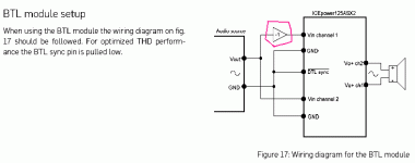
Unless I am totally blind I am not seeing where you need to be balanced going into the BTL input. Maybe I just need a second or third cup of coffee.
...need a second or third cup of coffee.
Or a read of the datasheet.
It indeed shows an inverter to get BTL operation. (Seems they maybe could have put it on-board, especially since there is a BTL mode for the oscillators, but...)
Attachments
Why 10K:10K instead of 600:600?
It is clear the input of the IcePower is well above 10K, so that will work.
It is not clear that a tube like amp will be happy driving a 600 Ohm winding (even un-loaded). Where 600r is required we usually use beefy tubes, 6V6 not twin triodes.
It would "work", but may be compromised in the bass.
However it is your project, do what you want.
So BTL is bridged operation from what I see on the diagram. Where does it show that is is balanced in? I see signal and ground for input on both channels but I don't see the +,-, and ground in for a true balanced input.
The diagram shows unbalanced input. The Ch1 gets an inverted signal and Ch2 gets a non inverted signal.
The diagram shows unbalanced input. The Ch1 gets an inverted signal and Ch2 gets a non inverted signal.
It is clear the input of the IcePower is well above 10K, so that will work.
It is not clear that a tube like amp will be happy driving a 600 Ohm winding (even un-loaded). Where 600r is required we usually use beefy tubes, 6V6 not twin triodes.
It would "work", but may be compromised in the bass.
However it is your project, do what you want.
Hi PPR
thanks for the clear explanation. I just wanted to know the correct impedance. I should change my transformers.
Because I already have an 600:10k transformer. I gave it a try. I removed the burrbrown balancer circuit and put the transformer. Now Bass is very heavy a little bit boomy. Trebles feels like in the background. Mids are beautiful but too much. Generally sound is very thick feels like frequency drops after 8-10khz.
What do you think about this?
- Status
- This old topic is closed. If you want to reopen this topic, contact a moderator using the "Report Post" button.
- Home
- Amplifiers
- Chip Amps
- Line input transformer for unbalanced to balanced conversion