After gathering some information from this Forum and from AN1192, I would like to discuss the options we might use for bridging and paralleling amplifier chips.
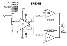
The central idea is to use a balancing chip, which can be the SSM2142, a DVR134 or any other, or perhaps a transformer, to buffer the amp chips from the pot. We might eliminate the cap and isolate the amplifying chips.
Bridging and paralleling might bring other benefits, like cancelling some distortions, etc.
Which amp chips you use is up to you.
We can also use lower voltages, like +/-15v or +/-18v, which would allow lower loads without the chips protecting themselves. It would also allow using batteries, for those that would like to try them. If we to higher voltages we will need to regulate the power we fit to the balancing chip.
For the most informed ones, you can see were we might be getting to: Rowland territory!!!
The first Rowlands use an input transformer to balance the bridge, though newer versions are eletronically balanced apparently. To simplify this step I'm using two quite known balancing chips, from BB and ADI.
The Rowland also uses non-inverted versions all over, but we can do that too.
My project involves designing pcbs to probably hold two complete bridges on each, which some links ready to parallel the bridges.
Comments and constructive critics, please!
Carlos
Attachments
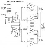
BRIDGE & PARALLEL
Here's the second option.
I'm jumping one stage, just paralleling two amp chips, to go to the most complete version.
The only difficult parts here are the 0.1% resistors National recommends for the paralleling. In fact they recommend using 0.1% resistors all over and also DC servos on each amp chip.
I think this might be a bit much, but building them will prove me right or wrong.
The second drawing could only go zipped. Sorry.
Carlos
Attachments
allright! this is what i was after! only thing i can see, is that with the balanced driver, BB recommends a buffer. there might be an easier way to do this, as there are three internal opamps and an addition buffer. i have no problem with opamps, but if kept to a minimum the sound should (hopefully) be a little better.
Hamish said:only thing i can see, is that with the balanced driver, BB recommends a buffer. there might be an easier way to do this, as there are three internal opamps and an addition buffer. i have no problem with opamps, but if kept to a minimum the sound should (hopefully) be a little better.
In my opinion, the BB or ADI chips can work as a buffers too. Remember that here they are only feeding inverted and non-inverted signals to the amp chips.
The internal opamps are obligatory, because if you want to go balanced you will need two or three chips to accomplish it anyway. The advantage here is that an important part of that differential output, the high precision resistors, are built in.
A transformer might be simpler than this, but a lot more expensive.
The only thing I designed in but I'm not quite sure how it will work is the pot. All designs I have seen with these chips, mostly mixers, put the output amp in between.
But I think it will work as it is now. I will try it, also adding buffers or lineamps before it to see what happens.
Carlos
Carlos
Wrong design
Sorry folks. Today I found out the bridge/parallel design I zipped and sent to the Forum was not the final one I had made.
Here's the correct one.
For those interested in seeing a different approach to paralleling OP549s, please have a look here:
http://www.diyvideo.com/forums/showthread.php?threadid=5318&pagenumber=3
Once again I apologize for my mistake above.
Carlos
Attachments

Hi,
We had this discussion off-line before.
My main concerns regarding the using the line driver chips are:
1) Quality of on board Chips and more importantly RESISTORS
2) Loss of the option for balanced inputs
I would champion still a transformer and if the positive measurable and audible effects from a transformer are undesirable or too expensive I would suggest that an electronically balanced input using Op-Amp's would be a better choice. In this case you have an input that behaves more or less like a transformer, allowing you to us ethe circuit with balanced or SE Inputs as you like.
And of course, an electronically balanced input can still be made to use Op-Amp Chips in Inverted mode, which would in effect allow you to simply add the "balancing" Op-Amp to the actual bridge circuit, taking the actual outputs of the Amplifier Chips as the point to balance. Simply use a really fast Op-Amp here (how about LM6181 or AD811) and the whole balancing process will happen at the speed of main Amp Chip. This would work well in the sense of "simplicity".
Also, in this case you have a fully free choice of the quality of resistors and op-amp's which will give you the ability to use for example high speed Video Amp's or the very nice sounding OPA627 (of course, three OPA627 readily cost as much as a decent transformer).
If you JUST want want an inverted drive to the second Amp from an SE source the easiest way is to use a sonically very transparent Op-Amp as simple gain of 1 inverter and to drastically simplify the circuit. In this case you could use a Dual Op-Amp and use the other halve as unity gain buffer.
Sayonara
The central idea is to use a balancing chip, which can be the SSM2142, a DVR134 or any other, or perhaps a transformer, to buffer the amp chips from the pot.
We had this discussion off-line before.
My main concerns regarding the using the line driver chips are:
1) Quality of on board Chips and more importantly RESISTORS
2) Loss of the option for balanced inputs
I would champion still a transformer and if the positive measurable and audible effects from a transformer are undesirable or too expensive I would suggest that an electronically balanced input using Op-Amp's would be a better choice. In this case you have an input that behaves more or less like a transformer, allowing you to us ethe circuit with balanced or SE Inputs as you like.
And of course, an electronically balanced input can still be made to use Op-Amp Chips in Inverted mode, which would in effect allow you to simply add the "balancing" Op-Amp to the actual bridge circuit, taking the actual outputs of the Amplifier Chips as the point to balance. Simply use a really fast Op-Amp here (how about LM6181 or AD811) and the whole balancing process will happen at the speed of main Amp Chip. This would work well in the sense of "simplicity".
Also, in this case you have a fully free choice of the quality of resistors and op-amp's which will give you the ability to use for example high speed Video Amp's or the very nice sounding OPA627 (of course, three OPA627 readily cost as much as a decent transformer).
If you JUST want want an inverted drive to the second Amp from an SE source the easiest way is to use a sonically very transparent Op-Amp as simple gain of 1 inverter and to drastically simplify the circuit. In this case you could use a Dual Op-Amp and use the other halve as unity gain buffer.
Sayonara
Re: Re: Bridgeclone
We certainly did, and I always enjoy most of them...
What balanced inputs are we talking about? The option I was considering was an unbalanced input stage with a balanced output that would feed the inverting gainclones.
Once again, I think we are discussing a balanced output here, not input.
What a transformer would bring, certainly a good thing, is galvanic isolation. The price to pay is ... the price. Good transformers are quite expensive and not easy to find. On the other side I do think you can get as good and measurable effects with transformerless stages too.
Implementing a balancing stage with two or three chips would be fine, as we now can get 0.1% resistors rather easily. It will just use a lot of space and would not be as straightforward as using the chips I suggested.
In order to make small pcbs for this project, that could be used in different ways and options, I opted for the single balancing chips.
OK. This would mean using a balancing stage as I suggested above. It seems these BB and ADI chips are not quite to your liking and/or prefer to ignore them.
Indeed! Also 0.1 % resistors do not come cheap.
I'd say something like an AD825/AD8610 or AD826/AD8620 might be used for this too. Some comments from this Forum recommended them as better sounding than 627s, but this might be a mere question of taste.
I think it's time I build these pcbs and see what I get. I was waiting for ideas to improve on my balancing/paralling suggestions.
Carlos
Kuei Yang Wang said:
We had this discussion off-line before.
We certainly did, and I always enjoy most of them...
My main concerns regarding the using the line driver chips are:
1) Quality of on board Chips and more importantly RESISTORS
2) Loss of the option for balanced inputs
What balanced inputs are we talking about? The option I was considering was an unbalanced input stage with a balanced output that would feed the inverting gainclones.
I would champion still a transformer and if the positive measurable and audible effects from a transformer are undesirable or too expensive I would suggest that an electronically balanced input using Op-Amp's would be a better choice. In this case you have an input that behaves more or less like a transformer, allowing you to us ethe circuit with balanced or SE Inputs as you like.
Once again, I think we are discussing a balanced output here, not input.
What a transformer would bring, certainly a good thing, is galvanic isolation. The price to pay is ... the price. Good transformers are quite expensive and not easy to find. On the other side I do think you can get as good and measurable effects with transformerless stages too.
Implementing a balancing stage with two or three chips would be fine, as we now can get 0.1% resistors rather easily. It will just use a lot of space and would not be as straightforward as using the chips I suggested.
In order to make small pcbs for this project, that could be used in different ways and options, I opted for the single balancing chips.
And of course, an electronically balanced input can still be made to use Op-Amp Chips in Inverted mode, which would in effect allow you to simply add the "balancing" Op-Amp to the actual bridge circuit, taking the actual outputs of the Amplifier Chips as the point to balance. Simply use a really fast Op-Amp here (how about LM6181 or AD811) and the whole balancing process will happen at the speed of main Amp Chip. This would work well in the sense of "simplicity".
OK. This would mean using a balancing stage as I suggested above. It seems these BB and ADI chips are not quite to your liking and/or prefer to ignore them.
Also, in this case you have a fully free choice of the quality of resistors and op-amp's which will give you the ability to use for example high speed Video Amp's or the very nice sounding OPA627 (of course, three OPA627 readily cost as much as a decent transformer).
Indeed! Also 0.1 % resistors do not come cheap.
I'd say something like an AD825/AD8610 or AD826/AD8620 might be used for this too. Some comments from this Forum recommended them as better sounding than 627s, but this might be a mere question of taste.
Well, in fact that's something I was willing to try, using a dual chip as you suggest, and compare it to the SSM and DRV chips.
If you JUST want want an inverted drive to the second Amp from an SE source the easiest way is to use a sonically very transparent Op-Amp as simple gain of 1 inverter and to drastically simplify the circuit. In this case you could use a Dual Op-Amp and use the other halve as unity gain buffer.
I think it's time I build these pcbs and see what I get. I was waiting for ideas to improve on my balancing/paralling suggestions.
Carlos
Re: A new bridged gainclone
This week I should be building these pcbs, then comparing results with different chips.
Kuei Yang Wang thinks an LM6182 would be a less noisy alternative. Unfortunately this chip was discontinued by National, but I have some to try and compare other chips to it.
Carlos
carlmart said:Following some off line suggestions from Kuei Yang Wang, here's a different implementation for a bridged/parallel gainclone.
Carlos
This week I should be building these pcbs, then comparing results with different chips.
Kuei Yang Wang thinks an LM6182 would be a less noisy alternative. Unfortunately this chip was discontinued by National, but I have some to try and compare other chips to it.
Carlos
Attachments
Hi Carlos,
Maybe I am missing something here, but why do you prefer the bridge/paralell configuration instead of the first bridge? Is just for the power or there is something else?
From what I read from NS, the output resistors will have to be precisely matched, which hads complexity to the design.
Miguel
Maybe I am missing something here, but why do you prefer the bridge/paralell configuration instead of the first bridge? Is just for the power or there is something else?
From what I read from NS, the output resistors will have to be precisely matched, which hads complexity to the design.
Miguel
miguel2 said:
Maybe I am missing something here, but why do you prefer the bridge/paralell configuration instead of the first bridge? Is just for the power or there is something else?
From what I read from NS, the output resistors will have to be precisely matched, which hads complexity to the design.
The idea behind this project is to make pcb modules that can be implemented according to your needs.
These chips have a limiting protection which won't allow you handle difficult loads (low impedance) and maximum voltage also limits the power. By paralleling you can take care of the hard loads and by bridging you can go higher in power. You take your pick.
I don't think precision matching would be a problematic issue. First nowadays you can get 0.1% resistors for a very reasonable price: e.g. have a look at Percy's catalog. Second you can also match your resistors quite well and the differences shouldn't be such a problem.
One thing that can be done is using a 100K trimpot on the non-inverting pin and zero DC offset. If I'm not wrong that's what Jeff Rowland does.
Carlos
BTW, what about this issue:
from:
http://www.diyaudio.com/forums/showthread.php?s=&threadid=13808
Me:
though i am new to this all, isn't the non inverting gain formula differnet then inverting gain. it looks like the gains would be different.
BrianGT:
This is true. The gain of the non-inverted amplifier is Av = 1+Rf/R1, and the gain of the inverted gainclone is Av = -Rf/R1. (R1 is the 10k in the picture, and Rfeedback is the 220k) This would mean that with the potentiometer at full signal, then the gain of the non-inverted would be 23, and the inverted would be -22. This issue could be fixed with a 230k resistor for Rf in the inverted amp.
Re: Re: A new bridged gainclone
Koinichiwa,
Now that this little thing has made it out into the open I would like to just make some comments. These, I hope will illustrate what aims and intentions where persued in this Circuit. There are many ways in which amplifiers can be bridged.
My PERSONAL favourite for a bridged "Gainclone" would be a good quality input Transformer (like the S&B TX-101 in 2:1 stepdown mode) providing the "phasesplitting" and being followed in each phase by two to four LM3875/3886 in parallel and in inverting configuration.
In virtually all Op-Amp's, even the very best Audio Op-Amp's, there is marked difference in measured distortion and in sound between inverting and non-inverting operation. Power Op-Amp chips are no difference. Hence the inverting configuration. I have a pair of TX-101 floaing about, if I ever get them back from being loaned out (unlikely) I might just give this whole thing a bash.
Carlos insited that the Circuit for "general" use MUST not use expensive transformers and/or Op-Amp's and should avoid complex circuits (eg servo balanced input) and have an unbalanced input ONLY and fairly high input impedance.
We bounced various ideas back and forth. My suggestion is shown above. First, we need to somehow buffer the Inputs of parallel "Inverted GainClones" (IGC). One Single Chip IGC has an input impedance of 10k. Two in parallel have 5k input impedance, four in parallel have 2k5 input impedance. If we bridge them using a balanced feed (however generated) we would have that input impedance per phase.
If we assume for a moment as example a balanced 4-Way parallel Bridged IGC (BIGC) we'd have an input impedance of 5k balanced. Using a 2:1 stepdown input transformer we would have around 20k input imput impedance and either balanced or unbalanced input options, and that at low distortion and with a very high degree of transparency.
Any other methode of providing the inverted phase requires extra active circuitry or mixing inverting and non-inverting mode. In the worst case it involves re-amplifying an already distorted signal, which will eliminate the distortion compensating properties of a "balanced" output stage.
To equal the transformer cheaper we need to give each phase as pure a feed as possibe and buffer per phase a 2k5 load at a little above 1V RMS for full output. While this may not SEEM like a difficult job, most so-called Audio Op-Amp's output stages will prefer not to drive such a load.
Using Transimpedance circuit derived Op-Amp's (LM6172 in this case, others exist) serves both to give good drive ability and excellent transparency. First, unlike ANY of the Op-Amp's (Power or small signal, integrated or discrete) transimpedance circuits do not suffer the common mode input signal induced rise in distortion in non-inverting mode. They perform in essence the same, inverting or not.
The LM6172 used as buffer or as inverter is very transparent, both measured and audible, with no rise of distortion in the audio band, in essence no slew rate limit of relevance in the audio range and extremely good drive ability. The transparency gets better if we make sure that both outputs are truely balanced with respect to the current drawn from them (see above) as now PSU line current modulations cancel, as long as the output stage quiescent current is larger than the peak current drawn (0.8mA per phase in our example).
As these Op-Amp's are designed to drive 1 - 2V RMS in a rather linear fashion int 100...150 Ohm loads at frequencies in the MHz range ding a litte bit of audio stuff is a doodle and very linear. Output peak current capabilities of up to 50..70mA (around 100 times the maximum required) mean a good deal of overkill and more crucially, good inherent linearity of the output stage.
One Op-Amp buffers the input and drives one of the phases directly. A second Op-Amp operates as a simple phase inverter with a gain of -1 and drives the other phase. It's output is loaded with an extra 10k resistor to ground to ensure that both outputs of the Dual Op-Amp have exactly the same magnitude but opposite phase/polarity output current.
One could have used the inverter circuit directly from the main input, but this would have lowered the input impedance to 10k. Re-amplifying the distortion of the first Op-Amp in follower mode is not really an issue, as it has very little Distortion. Driving non-inverted, unity gain, 0.33V RMS into 100 Ohm the distortion is > -110db for low order (2nd/3rd) harmonics with very little happening at higher order harmonics. The 2k worst case load in our Amplifier will reduce the distortion by another 6 - 10db. Adding the second amplifiers distortion will increase this in the worst case by 6db.
So the frontend of this circuit should have in the end an overall level of distortion no higher than -110db @ 10KHz or around 0.00033%. This should be sufficient low that the entire distortion characteristic of the complete amplifier is dominated by the LM3875/3886 Chips (0.05% THD @ 10KHz & 40W RMS).
I would still prefer a dual current feedback Op-Amp such as the discontinued LM6182 as it offers in my experience in a suitable circuit better (subjective and objective) performance.
I would think however that regardless of LM6172 or LM6182 when compared to off the shelf "balancing" chips this frontend will be less expensive and of much higher sonic performance. Following the "gainclone" philosophy the gainsetting feedback resistor(s) should be precision 1206 formfactor SMD types (maybe tantalum) soldered directly to the chip pins, close to the body of the Op-Amp, the other resistors to taste, though using the same SMD types would likely be a good choice.
BTW, such an 8 X LM3875 BIGC with 37V nominal+/-supply rails will deliver up to around 44V RMS into a high impedance load and up to 17A RMS current. Theoretically that would allow nearly 600W into 2 Ohm and 242W into 8 Ohm, so no small change. Of course, such power (especially into 2 Ohm) could be provided only on short peaks (as common in music) and not sustained as otherwise the various IC's would quickly go into thermal shutdown.
Anyway, this just as a little background as to the "why" of the circuit.
Sayonara
Koinichiwa,
carlmart said:
Following some off line suggestions from Kuei Yang Wang, here's a different implementation for a bridged/parallel gainclone.
This week I should be building these pcbs, then comparing results with different chips.
Kuei Yang Wang thinks an LM6182 would be a less noisy alternative. Unfortunately this chip was discontinued by National, but I have some to try and compare other chips to it.
Now that this little thing has made it out into the open I would like to just make some comments. These, I hope will illustrate what aims and intentions where persued in this Circuit. There are many ways in which amplifiers can be bridged.
My PERSONAL favourite for a bridged "Gainclone" would be a good quality input Transformer (like the S&B TX-101 in 2:1 stepdown mode) providing the "phasesplitting" and being followed in each phase by two to four LM3875/3886 in parallel and in inverting configuration.
In virtually all Op-Amp's, even the very best Audio Op-Amp's, there is marked difference in measured distortion and in sound between inverting and non-inverting operation. Power Op-Amp chips are no difference. Hence the inverting configuration. I have a pair of TX-101 floaing about, if I ever get them back from being loaned out (unlikely) I might just give this whole thing a bash.
Carlos insited that the Circuit for "general" use MUST not use expensive transformers and/or Op-Amp's and should avoid complex circuits (eg servo balanced input) and have an unbalanced input ONLY and fairly high input impedance.
We bounced various ideas back and forth. My suggestion is shown above. First, we need to somehow buffer the Inputs of parallel "Inverted GainClones" (IGC). One Single Chip IGC has an input impedance of 10k. Two in parallel have 5k input impedance, four in parallel have 2k5 input impedance. If we bridge them using a balanced feed (however generated) we would have that input impedance per phase.
If we assume for a moment as example a balanced 4-Way parallel Bridged IGC (BIGC) we'd have an input impedance of 5k balanced. Using a 2:1 stepdown input transformer we would have around 20k input imput impedance and either balanced or unbalanced input options, and that at low distortion and with a very high degree of transparency.
Any other methode of providing the inverted phase requires extra active circuitry or mixing inverting and non-inverting mode. In the worst case it involves re-amplifying an already distorted signal, which will eliminate the distortion compensating properties of a "balanced" output stage.
To equal the transformer cheaper we need to give each phase as pure a feed as possibe and buffer per phase a 2k5 load at a little above 1V RMS for full output. While this may not SEEM like a difficult job, most so-called Audio Op-Amp's output stages will prefer not to drive such a load.
Using Transimpedance circuit derived Op-Amp's (LM6172 in this case, others exist) serves both to give good drive ability and excellent transparency. First, unlike ANY of the Op-Amp's (Power or small signal, integrated or discrete) transimpedance circuits do not suffer the common mode input signal induced rise in distortion in non-inverting mode. They perform in essence the same, inverting or not.
The LM6172 used as buffer or as inverter is very transparent, both measured and audible, with no rise of distortion in the audio band, in essence no slew rate limit of relevance in the audio range and extremely good drive ability. The transparency gets better if we make sure that both outputs are truely balanced with respect to the current drawn from them (see above) as now PSU line current modulations cancel, as long as the output stage quiescent current is larger than the peak current drawn (0.8mA per phase in our example).
As these Op-Amp's are designed to drive 1 - 2V RMS in a rather linear fashion int 100...150 Ohm loads at frequencies in the MHz range ding a litte bit of audio stuff is a doodle and very linear. Output peak current capabilities of up to 50..70mA (around 100 times the maximum required) mean a good deal of overkill and more crucially, good inherent linearity of the output stage.
One Op-Amp buffers the input and drives one of the phases directly. A second Op-Amp operates as a simple phase inverter with a gain of -1 and drives the other phase. It's output is loaded with an extra 10k resistor to ground to ensure that both outputs of the Dual Op-Amp have exactly the same magnitude but opposite phase/polarity output current.
One could have used the inverter circuit directly from the main input, but this would have lowered the input impedance to 10k. Re-amplifying the distortion of the first Op-Amp in follower mode is not really an issue, as it has very little Distortion. Driving non-inverted, unity gain, 0.33V RMS into 100 Ohm the distortion is > -110db for low order (2nd/3rd) harmonics with very little happening at higher order harmonics. The 2k worst case load in our Amplifier will reduce the distortion by another 6 - 10db. Adding the second amplifiers distortion will increase this in the worst case by 6db.
So the frontend of this circuit should have in the end an overall level of distortion no higher than -110db @ 10KHz or around 0.00033%. This should be sufficient low that the entire distortion characteristic of the complete amplifier is dominated by the LM3875/3886 Chips (0.05% THD @ 10KHz & 40W RMS).
I would still prefer a dual current feedback Op-Amp such as the discontinued LM6182 as it offers in my experience in a suitable circuit better (subjective and objective) performance.
I would think however that regardless of LM6172 or LM6182 when compared to off the shelf "balancing" chips this frontend will be less expensive and of much higher sonic performance. Following the "gainclone" philosophy the gainsetting feedback resistor(s) should be precision 1206 formfactor SMD types (maybe tantalum) soldered directly to the chip pins, close to the body of the Op-Amp, the other resistors to taste, though using the same SMD types would likely be a good choice.
BTW, such an 8 X LM3875 BIGC with 37V nominal+/-supply rails will deliver up to around 44V RMS into a high impedance load and up to 17A RMS current. Theoretically that would allow nearly 600W into 2 Ohm and 242W into 8 Ohm, so no small change. Of course, such power (especially into 2 Ohm) could be provided only on short peaks (as common in music) and not sustained as otherwise the various IC's would quickly go into thermal shutdown.
Anyway, this just as a little background as to the "why" of the circuit.
Sayonara
theChris said:Me:
though i am new to this all, isn't the non inverting gain formula differnet then inverting gain. it looks like the gains would be different.
The different gain is an issue when you are using inverting and non-inverting circuit for the bridge, which is another way this can be done.
In this case the amps are all inverting, so there's no such problem.
Carlos
A new bridged gainclone
As usual, Kuei's comments will help many of us pay some attention to issues we never thought were that important.
It's strange how many people disregard the different behaviour of chips when inverting or non-inverting.
In spite of my "insistence" of using simpler solutions for this project, I will try some of the most "complicated" and try to report what are the audible differences.
To start with I will try different chips for the input, including some LM6182 samples I already have.
Carlos
Kuei Yang Wang said:
My PERSONAL favourite for a bridged "Gainclone" would be a good quality input Transformer (like the S&B TX-101 in 2:1 stepdown mode) providing the "phasesplitting" and being followed in each phase by two to four LM3875/3886 in parallel and in inverting configuration.
Carlos insisted that the Circuit for "general" use MUST not use expensive transformers and/or Op-Amp's and should avoid complex circuits (eg servo balanced input) and have an unbalanced input ONLY and fairly high input impedance.
As usual, Kuei's comments will help many of us pay some attention to issues we never thought were that important.
It's strange how many people disregard the different behaviour of chips when inverting or non-inverting.
In spite of my "insistence" of using simpler solutions for this project, I will try some of the most "complicated" and try to report what are the audible differences.
To start with I will try different chips for the input, including some LM6182 samples I already have.
Carlos
Re: A new bridged gainclone
Sayonara,
One note. Carlos already knows, but forgot to mention. The LM6182 (or two AD811's) are not a direct "drop-in" within this circuit.
The LM6182 or 2pcs AD811 require a resistor in the feedback loop of the follower, 1k will be just fine. Further, in the interrest of "speed" and "noise" the three 10k resistors around the inverter should be changed also to 1k. Using this approach will reduce the noise of the Input Circuit by around 12db, also the current feedback Op-Amp's have less distortion than their "added buffer on negative input" voltage feedback complements (LM6181/82 vs. LM6171/72 for example). Of course, non of this may be audible, though I think it is.
Lastly, in the interest of avoiding building FM transmitters instead of amplifiers, please place a very low inductance 1uF or larger capacitor directly across the +V and -V pins of the high speed op-amps (applies to AD811, LM6181/82/71/72 et al).
Other than that, tweak, experiment away and have fun.
Sayonara
Sayonara,
carlmart said:
To start with I will try different chips for the input, including some LM6182 samples I already have.
One note. Carlos already knows, but forgot to mention. The LM6182 (or two AD811's) are not a direct "drop-in" within this circuit.
The LM6182 or 2pcs AD811 require a resistor in the feedback loop of the follower, 1k will be just fine. Further, in the interrest of "speed" and "noise" the three 10k resistors around the inverter should be changed also to 1k. Using this approach will reduce the noise of the Input Circuit by around 12db, also the current feedback Op-Amp's have less distortion than their "added buffer on negative input" voltage feedback complements (LM6181/82 vs. LM6171/72 for example). Of course, non of this may be audible, though I think it is.
Lastly, in the interest of avoiding building FM transmitters instead of amplifiers, please place a very low inductance 1uF or larger capacitor directly across the +V and -V pins of the high speed op-amps (applies to AD811, LM6181/82/71/72 et al).
Other than that, tweak, experiment away and have fun.
Sayonara

I just found out I have couple of Lundahl transformers http://www.lundahl.se/pdfs/datash/1570_0xl.pdf
Would they work well with this setup?
Would they work well with this setup?
Koinichiwa,
They would sort of work, but are really by far too low impedance to work well in a lineinput. The LL7901/7902 is what you'd be better looking at, if it has to be lundahl.
Sayonara
Peter Daniel said:I just found out I have couple of Lundahl transformers http://www.lundahl.se/pdfs/datash/1570_0xl.pdf
Would they work well with this setup?
They would sort of work, but are really by far too low impedance to work well in a lineinput. The LL7901/7902 is what you'd be better looking at, if it has to be lundahl.
Sayonara
- Status
- This old topic is closed. If you want to reopen this topic, contact a moderator using the "Report Post" button.
- Home
- Amplifiers
- Chip Amps
- Bridgeclone