Well, I decided to look into this Bridgeclone thing, since I have a lot of heatsinks sitting around that I have been stocking up for the past 2 years... and I also have a bunch of gainclone pcbs.
Here is my proposed project (just started seriously considering it today at lunch time):
-Bridged-parallel configuration with 3 paralleled LM3875 amplifiers in non-inverted configuration on each side of a Balanced line driver, like the SSM2142 from Analog Devices, for a total of 6xLM3875 per channel.
-1kVA 4x25 (seperate bridge setup for each channel)
-output of each amp tied together via a 0.22ohm resistor (have them left over from the group order for the AlephX). The resistors on the boards will all be matched to < 0.1% No servo is planned.
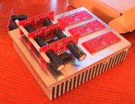
-As far as the chassis, I am thinking of stacking them as shown in the below picture, with 3 or 6 channels per heatsink (will see how the heat dissipation is with 6 is first, then scale down to 3 if necessary)
I will give this a try in a week or so, after I finish getting the kits shipped out for my current group order.
Any one have any comments/suggestions for this project? I spoke with National, and they said that the LM3875 will work just fine in the BPA200 configuration, but with a bit less power and heat dissipation per chip. They recommend the uninsulated package for this application, as the heat dissipation is the main limiting factor for this design. (TF shown in picture, as I had the boards already assembled, sitting around)
Pictures of my pcbs from the group order:
http://brian.darg.net/gallery/nigc-kit
--
Brian
Here is my proposed project (just started seriously considering it today at lunch time):
-Bridged-parallel configuration with 3 paralleled LM3875 amplifiers in non-inverted configuration on each side of a Balanced line driver, like the SSM2142 from Analog Devices, for a total of 6xLM3875 per channel.
-1kVA 4x25 (seperate bridge setup for each channel)
-output of each amp tied together via a 0.22ohm resistor (have them left over from the group order for the AlephX). The resistors on the boards will all be matched to < 0.1% No servo is planned.
-As far as the chassis, I am thinking of stacking them as shown in the below picture, with 3 or 6 channels per heatsink (will see how the heat dissipation is with 6 is first, then scale down to 3 if necessary)
I will give this a try in a week or so, after I finish getting the kits shipped out for my current group order.
Any one have any comments/suggestions for this project? I spoke with National, and they said that the LM3875 will work just fine in the BPA200 configuration, but with a bit less power and heat dissipation per chip. They recommend the uninsulated package for this application, as the heat dissipation is the main limiting factor for this design. (TF shown in picture, as I had the boards already assembled, sitting around)
Pictures of my pcbs from the group order:
http://brian.darg.net/gallery/nigc-kit
--
Brian
Attachments
Banned
Joined 2002
moe29 said:This should be a new thread... not at the tail end of an old thread.
what would be the approx. output of a bridge with 6 chips?
I will make a new thread in the future, once I decide to prototype this thing.
I am guessing that it would put out around 200W+ into my 4 ohm speakers, if my math is correct.
Here is what I figured:
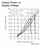
If my speakers are 4 ohm, each side of the bridged configuration sees 2 ohms, of which each one of the parallel amps sees a 6 ohm load, since there are 3 of them in parallel. For a 6 ohm load, and the 34vdc power supply rails that I will provide the channels with, I am guessing that it will provide around 65watts each (based on table below), making a total of 390watts theoretical maximum based on the datasheet and the BPA200 application note. I would expect this to be lower (300watts), based on the heat dissipation limits of the chips, and other considerations, such as power lost to the .22ohm resistor on the output, and the limiting power output of the 1kVa transformer.
The calculations also lean towards around 200watts into an 8ohm speaker.
I am not looking to obtain these high of numbers, as a single 1kVA transformer for 2 channels probably won't be enough for that much power. I certainly do not want to buy anymore transformers.
Calculations are based off the below chart from the LM3875 datasheet along with the information in the BPA200 app note. Please correct me if I made incorrect assumptions, as I only seriously started thinking about this today.
--
Brian
Attachments
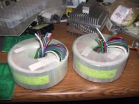
The transformer picture on the right, in the picture below, is the one that I am looking to use for the prototype, 1kVA, 4x25vac, originally for an Aleph I was looking to build (similar to an Aleph 5). It also has a faraday shield between the primary and secondary windings. I bought it from Victoria Magnetics over a year ago, when I was all ready to build Class A amps. I was co-oping during school, and when school started up again, I had no time to finish them. Once time became available, the gainclone shifted my interest away from the Class A. Sure it is a girly chipamp, but it can run on far less power, much less heat dissipation, and still sounds decent.
--
Brian
--
Brian
Attachments
BrianGT said:-Bridged-parallel configuration with 3 paralleled LM3875 amplifiers in non-inverted configuration on each side of a Balanced line driver, like the SSM2142 from Analog Devices, for a total of 6xLM3875 per channel.
Any one have any comments/suggestions for this project?
I am planning something similar, a PA100 made of 2 boards/channel. You seem to have adressed all the possible pitfalls I thought of.
About the only thing that comes to mind is to use a DRV134 instead of an SSM2142. They have been reported to sound better.
Banned
Joined 2002
moe29 said:This should be a new thread... not at the tail end of an old thread.
what would be the approx. output of a bridge with 6 chips?
Well aren't you just calling the kettle black.... you telling people that it should be a NEW THREAD THEN ASKING A QUESTION.. HUMM.....!!!
leadbelly said:
I am planning something similar, a PA100 made of 2 boards/channel. You seem to have adressed all the possible pitfalls I thought of.
About the only thing that comes to mind is to use a DRV134 instead of an SSM2142. They have been reported to sound better.
Well, I ordered samples of both chips today, but the DRV134 is surface mount, and I only have a single adapter to use with it.
The SSM2142 seems easier to use since it is DIP. Maybe I will order another SMD adapter...
--
Brian
BrianGT said:
Well, I ordered samples of both chips today, but the DRV134 is surface mount, and I only have a single adapter to use with it.
The SSM2142 seems easier to use since it is DIP. Maybe I will order another SMD adapter...
--
Brian
?
The DRV134 comes in 8 pin DIP, and I just punched it into Digikey and they're in stock.
leadbelly said:
?
The DRV134 comes in 8 pin DIP, and I just punched it into Digikey and they're in stock.
I got confused with the AD815, which is only in SMD. I will try getting some of the DRV134 and trying them out.
Thanks for correcting me.
--
Brian
tbla said:
can the DRV-134 or similar chips be driven directly by a source with a volume control before it, ..or would a buffer be required to deal with the low input impedance of the line driver chip?
ideas ??

zobsky said:
can the DRV-134 or similar chips be driven directly by a source with a volume control before it, ..or would a buffer be required to deal with the low input impedance of the line driver chip?
ideas ??
my amplifier uses the DRV134 input connected through a 10k resistor to the wiper of a 10k pot across the input, giving volume control. it seems to work fine.
i read a bit of this thread, and maybe asking a question a few people have on their minds (or maybe its just me): would it be possible to use Brian's boards for a bridgeclone? the idea of a 2-chip amp for a small sub seems quite interesting. just add the drv chip setup. i'm sure i'm oversimplifying it and missing something though....
SQ Kid said:i read a bit of this thread, and maybe asking a question a few people have on their minds (or maybe its just me): would it be possible to use Brian's boards for a bridgeclone? the idea of a 2-chip amp for a small sub seems quite interesting. just add the drv chip setup. i'm sure i'm oversimplifying it and missing something though....
How many posts per page do you have in your preference settings, because in my browser, the post with pictures Brian put up IS ON THIS VERY PAGE

SQ Kid said:i read a bit of this thread, and maybe asking a question a few people have on their minds (or maybe its just me): would it be possible to use Brian's boards for a bridgeclone? the idea of a 2-chip amp for a small sub seems quite interesting. just add the drv chip setup. i'm sure i'm oversimplifying it and missing something though....
I think this is an excellent question. I don't have the printed boards, but just how easy is it to bridge two amps together?
I'm learning alot, but some of the finer details excape me at this point.
Bridging two boards shouldn't be very difficult. Basically, you need to feed the two boards with some sort of balanced source, and add a current matching resistor (I think this is what they are called) to the output of each chip. These resistors help keep current from flowing back and forth between the chips. It is also very important that all of the components in both boards are very closely matched. If this is not done, the two sides of the bridge will be out of balance, and will create distortion and possibly osscilation.
As far as feeding the two boards with a balanced soure, you could use a balancing transformer, a BB DRV134, or even something like a 12AT7 as a phase splitter. There are many options for this. If price is an issue, using the DRV134 is definately the way to go. This chip outputs a balanced signal and is very easy to implement in to this circuit. Just follow the chip's white paper. A transformer balanced input would be the way a botique pro gear manufacturer would do it, but quality input transformers can be very expensive. Lastly, a tube input would be a very interesting thing to try. I wish I understood tubes enough to come up with a circuit for this, as I am really itching to try this option. The advantage to the tube phase splitter is a smoother, warmer, "tubier" sound. Some people like this sound, and some people don't. The tube circuit will exhibit higher distortion than the DRV134, but it is primarily even-order and still sounds very good when well implemented.
If any tube guys are lurking here, I'm sure we would all appreciate some help with a tube phase splitter to drive both sides of a bridged gainclone.
Cheers,
Zach
- Status
- This old topic is closed. If you want to reopen this topic, contact a moderator using the "Report Post" button.
- Home
- Amplifiers
- Chip Amps
- Bridgeclone