Hello !
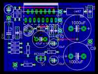
Here's a little Gift, it's a TDA7293 board designed on eagle.
It includes the created library on the zip file.
The board features the clipping indicator led, and a logical input to wake up the amp.
Attention, you MUST apply a signal in VL in order to make the amp play. If you don't want this, you can increase R10 to 10K value and connect it to +Vs.
The top routes (red) are jumpers.
Gain is 33, and there's a 2k2 / 22k divisor on the input, I did this way to avoid external oscilations.
It runs solid, no oscilations at all.
Press RASTNEST to show the common ground
I hope you enjoy it ! I would like to have feedback from the community.
Best Regards
Attachments
Hi nando.
I don't mean to rain on your parade but the two decoupling caps right next to the power pins are all but useless because they are grounded so poorly.
If you went for a double sided board you could have at least used the top layer as a nice contiguous ground plane and saved some room for the other traces on the bottom layer.
Hi nando.
I'm talking about C6 and C7, the film caps. They are connected to the ground plane right above C12. Look at the path current has to take in order to go from the ground connection of the film caps back to the power supply ground between the large electrolytic caps. That is not good decoupling at all.
Your layout would be much better if you rotated C10 90 degrees clockwise, rotated C9 90 degrees counterclockwise, moved the V+ and V- through holes out to the edge of the board, and rotated C6 and C7 90 degrees counterclockwise so that there is a very short ground path between the ground of the electrolytic caps and the film caps.
Brian, are you sure that a very low impedance ground is needed for these caps? As I know, they are only for decouple high impedance, so I thought that it would work fine this way. At least my amp runs without any oscilation, it's performing very well indeed, no noises or any problems.
Would you mind modifying the board layout to show your idea?
Your opinion is always wellcome.")
Would you mind modifying the board layout to show your idea?
Your opinion is always wellcome.
Very nice amp, dead silent, the mute function works amazingly well, it's a pleasure at every power time, as it slowly increases the volume level untill get full volume (RC time). GREAT.
BUT... ONE chip doesn't handle easily +/- 40v @ 8 Ohms. It gets HOOOT, I'll parallel this latter, then it will be perfect.
BUT... ONE chip doesn't handle easily +/- 40v @ 8 Ohms. It gets HOOOT, I'll parallel this latter, then it will be perfect.
-_nando-_ said:Brian, are you sure that a very low impedance ground is needed for these caps? As I know, they are only for decouple high impedance, so I thought that it would work fine this way.
Yes. The caps decouple high frequencies, not high impedance and the ground return path is every bit as important as the positive current path.
-_nando-_ said:Would you mind modifying the board layout to show your idea?
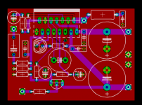
Attached is slightly modified version of your layout showing better placement for the power supply caps and better routing for the power supply traces. Since you were already using two layers I made the top layer ground. If I were making a PCB based on this chip, I would start the layout from scratch and begin laying out the power supply section first.
Download the file and change its name to "nando_mod.brd" so you can open it with Eagle.
Attachments
- Status
- This old topic is closed. If you want to reopen this topic, contact a moderator using the "Report Post" button.
- Home
- Amplifiers
- Chip Amps
- My GIFT for you: TDA7293 board + extras