I have heard that multiple TPA6120 in parallel can make a really good amp, but cant find a schematic anywhere. Any ideas? Would the chips be simply wired in parallel, or is it more complicated? I planned to glue a stack on top of each other, then just run wires down the sides to connect the pins.........
These are regular op-amps, you can't parallel them pin by pin. Build them as seperate but identical amp blocks (with proper heatsinking as described in the datasheet) and combine the outputs of channels/chips with current sharing series resistors (these are needed anyway, the TPA6120 hates to see *any* output capacitance). Follow the advice given in the datasheet exactly, these chips aren't easy to tame.
Plus, take a look at AN-1192 from National Semiconductor for concept and practice of paralleling op-amps.
- Klaus
Plus, take a look at AN-1192 from National Semiconductor for concept and practice of paralleling op-amps.
- Klaus
why? I plan to put small fins inbetween them if its heat concerns. I like the much shorter conection lengths of doing it this way, and saves me making pcb's.
edit- the why was to why i shouldnt stack them, second reply appered when i was typing!
edit- the why was to why i shouldnt stack them, second reply appered when i was typing!
Well I"m no expert but off of the top of my head i can think of a few reasons why stacking isn"t the best way to paralell opamps....
first is that each opamp will also see the input resistors in paralell which in effect will produce half the gain....so be sure that the opamps are stable at that gain...
also there should be a resistor on the output of each opamp before the signals combine so that each opamp shares the drive more equally......
opamp stacking is something that is done by a lot of DIY effects pedal makers as it can add different distortion which isn"t the best feature for an audio amp....Pluss with some opamps it simply just doesn"t work well for some reason.....
I guess you could give it a try , It might work fine or it might not...
it is simple to make a pcb useing a basic opamp configuration, you could probably just use a sharpie and draw the curcuit on to Pcb and etch....that is what I do for simple curcuits....
good luck
I think SuzyJ is working on a similar project for a tweeter amp.
Sounds like a cool project, but them bugs are hard to belly weld.
http://www.diyaudio.com/forums/showthread.php?s=&threadid=107516
Sounds like a cool project, but them bugs are hard to belly weld.
http://www.diyaudio.com/forums/showthread.php?s=&threadid=107516
KSTR said:combine the outputs of channels/chips with current sharing series resistors
- Klaus
What is the theroy behind a small resistance current sharing R?
Panson,
These Rs let you have control over the cross current flow between amps because you always have offsets and/or gain mismatches. One can make use of these normally unwanted currents though, to get some form of class A operation:
http://www.diyaudio.com/forums/showthread.php?postid=1258047#post1258047
With the TPA6120 (aka THS6012, btw) one must use 10R...100R series isolators anyway.
There are other schemes to "parallel" op-amps to increase output current, like master-slave configs (see the app-notes of the chip makers).
- Klaus
as pointed out above, opamps cannot be pin-to-pin paralleled
they have to have separate feedback loops and output current sharing resistors due to their differing open loop gains and input offset V, even op amps on the same die in a dual/quad don't match well enough
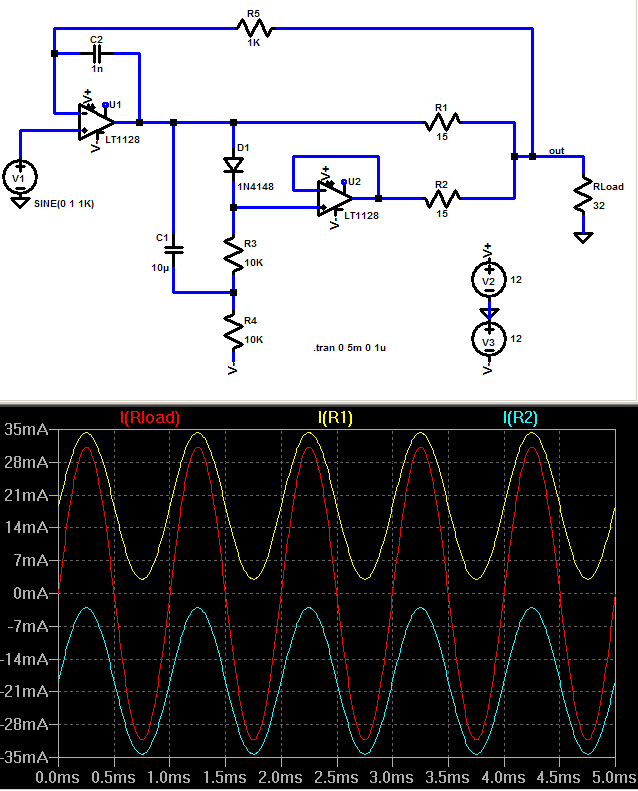
I have paralleld tpa6120, and biased them into push=pull Class A:
http://www.head-fi.org/forums/showthread.php?t=190991
posts 13,19 shows the heatsinking, 16 a simplified simulation of the otuput paralleling/Class A bias
they have to have separate feedback loops and output current sharing resistors due to their differing open loop gains and input offset V, even op amps on the same die in a dual/quad don't match well enough
I have paralleld tpa6120, and biased them into push=pull Class A:
http://www.head-fi.org/forums/showthread.php?t=190991
posts 13,19 shows the heatsinking, 16 a simplified simulation of the otuput paralleling/Class A bias
Here's what I'm working on. Please bear in mind that it's a design only so far - I haven't built one yet, so don't know how well it works (or even if it works at all!). It uses four TPA6120 chips, for a total of eight amplifiers. It's designed to drive loads of around 8 ohms, and should be good for somewhere around 10W RMS, using +/-15V supplies.
The PCB is nothing special - 3" long by 2.3" wide, double sided. Of course it uses mainly surface mount parts.
If you want more power than 10W, you could always build four, and connect them as parallel bridged pairs. Should be able to manage something like 40W RMS into 8 ohms like that.
The PCB is nothing special - 3" long by 2.3" wide, double sided. Of course it uses mainly surface mount parts.
If you want more power than 10W, you could always build four, and connect them as parallel bridged pairs. Should be able to manage something like 40W RMS into 8 ohms like that.
Attachments

wow, cheers for the help guys.
When I said about stacking chips I did mean to wire them in parallel, but physical stack the chips, with resistors solderd directly to the pins that couldnt just be stacked. I know the assembley would be very tricky, perhaps impossible, but it also seems like the it would give the best finnished amp if I could do it.
It was the amp that suzyj was talking about that inspired me!
If I made the same board is there any reason to use surface mount stuff? (Apart from the TPA's obviously) I have limited experience with SMD, but dont have the equipment and dont like doing it!
As for the pads underneath, my plan to solder them is to drill a small hole under the chip, tin the pad before fitting the chip and solder from under the chip through the hole. Dont know if any one has any better ideas, but I have heard a lot of people having problems with the heatsink pad, and this seemed like an obvious way of doing it to me..........
or just flip the chips upside down and use a heatsink on top, as with the link jcx posted above, doh, I should read things before i start typing away......
suzyj,
by eyeball your thermal pad soldering hole looks bigger than the thermal pad - TI has poor/misleading drawingings some places but you should find a dimensioned solder pad drawing which shows a much smaller exposed pad on the bottom - I'd try 0.080" (2mm) as max thru hole that doesn't overlap thermal pad boarders
actually I'd really just put the chips on upside down again, many CPU/Memory/Graphic chip cooler options with clamps or thermal conductive glue are easily adapatble - but don't short out the pins with silver filled compounds, be very careful with them or use ceramic filled epoxy or grease
I used 1 Ohm current sharing resistors - extra hf impedance from ferrite bead core on output may be needed to isolate cable Cload which could cause high frequency instability (10's MHz)
I don't like narrow gnd fill spacing, "fringing" capacitance adds up suprizingly quickly - and CFA op amps are highly allergic to any stray C on the negative input node - see the demo board layout
jcx,
nice project you did there, 4-layer PCB and all... that "current pump with offset" also is a very interesting solution for the input-CM range problem. I'd definitely be interested in the whole schematic (and I know it will not quite resemble the principle schem you shared). Did you spice-sim the stuff, with the THS6012 model?
A bunch of these TPA/THS in a bridged parallel class A config also would make a great amp for high efficiency mid/treble horns, say, with a BMS 4529 2" coax driver...
- Klaus
jcx said:suzyj,
by eyeball your thermal pad soldering hole looks bigger than the thermal pad - TI has poor/misleading drawingings some places but you should find a dimensioned solder pad drawing which shows a much smaller exposed pad on the bottom - I'd try 0.080" (2mm) as max thru hole that doesn't overlap thermal pad boarders
actually I'd really just put the chips on upside down again, many CPU/Memory/Graphic chip cooler options with clamps or thermal conductive glue are easily adapatble - but don't short out the pins with silver filled compounds, be very careful with them or use ceramic filled epoxy or grease
The holes are 0.125". They're bigger than the pads on the underside of the TPA6120. The plan was to solder the TPA6120s to the board like a normal SOIC, put short pieces of 1/8" brass rod through the holes with some thermally conductive goo, then clamp the whole board to a small heatsink on the other side. It accomplishes much the same as you've done with your dead-bugs, but without bending the pins.
jcx said:I used 1 Ohm current sharing resistors - extra hf impedance from ferrite bead core on output may be needed to isolate cable Cload which could cause high frequency instability (10's MHz)
I don't like narrow gnd fill spacing, "fringing" capacitance adds up suprizingly quickly - and CFA op amps are highly allergic to any stray C on the negative input node - see the demo board layout
Thanks for the tips. The fill spacing is 15 mils. I might push it away from the negative inputs a little.
jcx said:suzyj,
I don't like narrow gnd fill spacing, "fringing" capacitance adds up suprizingly quickly - and CFA op amps are highly allergic to any stray C on the negative input node - see the demo board layout
I agree with jcx we used these devices at work and they perform very well but they are very fast and require due care especially with regards to stray capacitance.
Watch out for stray capacitance from the ground plane below the device too.
The document he revered to is (slou 169)
from Ti. you will find that their DC offset could be a problem unless the feedback resistors are kept to small values (Ok a speaker is less of a problem than mW rated headphones).
Yes, the offset is quite high but the input bias current is in the uA region and can be as much as 12 uA.

and now the schematic package is attached as well.
Meantime some significant improvements were performed:
The amp has got a new fully symetrical input stage (w OPA1632) and the output resistors were decreased from 10R to 2R. So the total outout resistance is already only 0.1 Ohm.
Meantime some significant improvements were performed:
The amp has got a new fully symetrical input stage (w OPA1632) and the output resistors were decreased from 10R to 2R. So the total outout resistance is already only 0.1 Ohm.
Attachments
- Status
- Not open for further replies.
- Home
- Amplifiers
- Chip Amps
- parallel TPA6120?