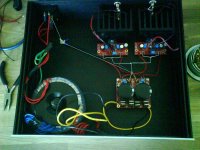
I have finished my kit, and after having som hum problems I found a grounding picture from carlosfm. I have changed the ground according to that picture.
I have included a picture which shows where the ground goes in my amp. Can anyone help me get rid of the hum please?
Can you see any problems?
I do not have any hum when there are no RCA cables connected (i.e. no source)
I have included a picture which shows where the ground goes in my amp. Can anyone help me get rid of the hum please?
Can you see any problems?
I do not have any hum when there are no RCA cables connected (i.e. no source)
Attachments
Posted this response to another hum problem above. I had a four channel amp with hum. Due to ground loop. I think there is a loop that goes from one channel, through the signal ground, to your source, then back through the signal ground of the other channel. Try tying the two signal input grounds together at the RCA jacks and then linking this to the chassis at that point. You can then tie this chassis earth to the safety earth that should be very close to your ac power input. If there is a loop, it should loop back before getting to your amp stage.
Tube amps are very susceptible to hum, so it is worth searching for tube amp grounding to give you some tips.
Cheers,
Chris
Tube amps are very susceptible to hum, so it is worth searching for tube amp grounding to give you some tips.
Cheers,
Chris
Thats a problem which I had before lots of time.
I gues your problem is;
- You have one PSU and two seperated amp board.
- So you have one GND from signal line on each amp board.
- One GND from PSU on each board.
- However theyre going to the same place sooner or later.
That means you have a gorund loop. My solution; If you will make a stereo amp then;
Make a single amp PCB and put a star gorund point to it, JUST ONE GND.
Or make a dual mono amp, seperated trafos, seperated PSUs and seperated amp boards.
You dont have any hum while you have no signal cable on inputz, because WITHOUT any signal source, a signal cable works as an antenna even its shilelded. Because if you dont carry anything on shield then its also an antenna.
Hi,
It's the LOOP that acts as an antenna for the electromagnetic fields around all electrical equipment and cabling.
If you eliminate the LOOP, you get rid of the hum caused by the loop. There may still be residual hum from other sources that are modulating the quiet/clean audio ground.
Alternatively if you minimise the AREA of the LOOP you attenuate the hum.
Finally, I rarely see it, but Dr Cherry drew up a typical PCB layout where he addressed specifically interference effects. LOOP AREAS on the PCB were minimised and/or of opposite phase to cancel each other. He also used a triple trace along the middle of this demo PCB. The power ran +ve, ground, -ve immediately adjacent to each other and all the tappings for the amp ran to either side of this triple strip. Again this is fairly unusual, since most PCB designers maximise the PSU LOOP AREA by running +ve and -ve on opposite sides of the PCB and keep ground at one end, running long traces to other locations that must increase inductance.
") ). The more you learn, the more there is to learn...
). The more you learn, the more there is to learn...
- Status
- This old topic is closed. If you want to reopen this topic, contact a moderator using the "Report Post" button.
- Home
- Amplifiers
- Chip Amps
- Hum on BrianGT kits.....