Hello All,
I am hoping someone can recomend a place to find a special socket or another way to do this.
Many people use 8 pin DIP sockets to roll op amps. I am looking for a quality socket (for OPA627) that can also allow me to plug in a resistor or other components or circuits that have pins the same size as a resistor, in conjunction with the op amp. This allows me to bias the op amp with several methods to find the best sounding configuration.
There isn't much room below the PCB for longer pins and soldering circuits underneath, so I need something that allows all connections to the socket to be made on top of the PCB. The op amp area on the PCB is also crowded making it hard to change connections below the sockets. Also if it was a high quality socket so it can be permanent without much of a compromise with soldering vs this method of attachment, that would make my day.
I have already removed the op amps and tried to solder them back in with a small circuit attached to two of the pins of the op amps and it was a disaster. PCB has taken a beating and another op amp is toast. Plaeae send me in the right direction with a better way to achieve this or a place where I can find these.
If there is nothing like this, also, please let me know. It is discouraging when you ask for help (and you have done the research and I did) and hundreds read the post and nobody replies. So please do in a helpful manor!
Thank You!
Regards//Keith
You can use such:
http://www.elfa.se/elfa-bin/dyndok.pl?lang=se&vat=0&dok=156472.htm (Please switch over to english)
Connector strip that can easily be broken off to chosen length. Stackable.
Pitch: 2.54 mm.
Application:
— Special IC sockets
— QIL sockets
— Test points
Insulating body: Glass-filled polyester (UL94V-0)
Socket contacts: Beryllium copper, gold-coated
Pins: Brass, tin-coated
Not sure exactly what you're after, and I don't' know of any sockets that allow for "extra" parts in addition to the op-amp. It's pretty common to install surface mount resistors and such between the pins of a through-hole DIP part, then plug it into a socket or just solder it in a board. They also sell 8-pin DIP pin-pin headers that allow you to solder resistors and such between the pins, then plug the assembly into a standard 8-pin socket. That's how the crossover frequencies are set on my Marchand active crossover boards. 1/8W resistors are neatest, but 1/4W just fit. To save the board, you need to permanently install some good sockets and be done with it. Then, either solder parts to the op-amps and plug them in, or even build up the op-amp and parts on the above described pin-pin header, and plug that in. Google Samtec for every kind of small pin related thing known to man, plus Mill-Max for those and sockets.
KP11520 said:Hello All,
I am hoping someone can recomend a place to find a special socket or another way to do this.
Many people use 8 pin DIP sockets to roll op amps. I am looking for a quality socket (for OPA627) that can also allow me to plug in a resistor or other components or circuits that have pins the same size as a resistor, in conjunction with the op amp. This allows me to bias the op amp with several methods to find the best sounding configuration.
Thank You!
Regards//Keith
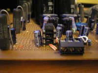
This is what I use to bias and unbias op amp
Attachments
Gentlemen,
Thank you for your responses!
Conrad, you must be Psychic or something.... You are right about saving the board! My next thread will be "how to repair solder pads!" I was against sockets being an amatuer purist, now I see the necessity (by disaster) and want to just make sure I find some that are as close to soldering as possible.
Funny, Mil-Max is about 12 miles away. I called to ask if they sell retail at a parts counter. No only samples or a referral to a distributor.
In my searches I see headers and wire wraps. They all just show the part only and not how it is used so I have no idea how to use them. jaudio thanks for the pics! I was thinking to get wire wrap sockets and run wire beneath the PCB from the appropriate pins to a 2 dip socket mounted somewhere out of the way for plugging and changing different value resistors and JFET Cascodes.
Then I was also thinking to buy 10 pin open frame dip sockets and cut the 2 end pins off and solder wire from the sockets of the op amp pins to the two unused sockets for plug and play as well.
Now I have to try to understand the Socket and Header configuration and solder in some excellent sockets and be done with it just as Conrad says. You can tell I have been doing research on this when you see some ofthe things I have read in my searches. I will post one from a respected source that might influence socket use among DIYers!
http://ieeexplore.ieee.org/xpl/freeabs_all.jsp?arnumber=1135481
As usual, I am searching for the best answer, I hate making mistakes!
Sometimes I realize there is a creativity side to this just like Home Remodeling and Carpentry. There is no textbook answer to everything, you need to inject creativity, logic and common sense into some situations for your own answers. (But if it works, get a patent).
Then again, Mama said...
Thanks!
Regards//Keith
After doing more searching, Andrew, I still don't understand how to build what you propose, can you kindly add more details so I can understand enough to decide whether I can handle it and get quality results? I understand what Conrad proposes but that entails some very delicate soldering work and I am afraid to solder directly to the pins of the op amps because they don't like the heat. I also have some nerve damage from a surgery last year that affected both my hands, so until that heals, delicate work is very frustrating and sometimes ugly and costly.
jaudio has a good idea but the jfet cascode is much larger than the op amp and wouldn't fit under the op amp like a small resistor and I wonder if each socket that gets added degrades the quality of the signal a little more.
I know I want gold but which kind of socket (machined, etc.) give the best contact when the op amp is inserted? Also, anybody know where I can get some more OPA627APs?
Thanks guys!
Regards//Keith
An externally hosted image should be here but it was not working when we last tested it.
http://www.headphoneamp.co.kr/ftp/sijosae/Gallery/
Hi Nordic.
Nice little circuit! Did you construct that?
The hyperlink is very informative and I saw a picture with a "Class A Socket". I think I can modify a 10 dip or the next size up from an 8 dip and run leads inside the frame to the last two sockets for inserting resistors and jfet cascodes for testing with the op amp inserted. Of course I will have to cut off the 2 end pins and put insulators protecting the metal contacts from the PCB, but this looks like a good "one level" option! Thanks!
Is that your cat? Does he like tennis or was that another DIY project? That Poor Cat! Actually it is a cute pic. I have had cats all my life, unfortunately, I can't have them any more because of some meds I am taking.
Regards//Keith
 ...
...
He's a beauty! Cool eyes! I am evvious!
This is a very good idea as mentioned above: http://www.headphoneamp.co.kr/ftp/sijosae/Gallery/Converter/Class-A.jpg
This is also a great idea: http://www.headphoneamp.co.kr/ftp/sijosae/Gallery/Converter/Multiloop.jpg
Thanks again for the hyperlink! A picture paints a thousand words!
Regards//Keith
This is a very good idea as mentioned above: http://www.headphoneamp.co.kr/ftp/sijosae/Gallery/Converter/Class-A.jpg
This is also a great idea: http://www.headphoneamp.co.kr/ftp/sijosae/Gallery/Converter/Multiloop.jpg
Thanks again for the hyperlink! A picture paints a thousand words!
Regards//Keith
What jfet are you going to use? Maybe you can run the transistors leads under the socket,that is if you have room on the sidesKP11520 said:
jaudio has a good idea but the jfet cascode is much larger than the op amp and wouldn't fit under the op amp like a small resistor
I read somewhere that,somebody might have heard a slight degradationKP11520 said:
I wonder if each socket that gets added degrades the quality of the signal a little more.
KP11520 said:
I know I want gold but which kind of socket (machined, etc.) give the best contact when the op amp is inserted?
Machined has best contact. I have the hardest time getting the op amp out of this socket,tightier fit better contact(IMHO)
Hi,
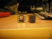
those pics show a socket converted to act as both header and socket.
the advantage of that is the DIP opamp can still plug into the empty sockets.
A header is similar but has pins on both top and bottom.
This allows components to be soldered to top side and then plugged into a dip socket. This needs a purpose designed PCB to accomodate the header mounted passive components alongside the opamp location.
Hi jaudio and Andrew,
Thanks for the feedback on the machined sockets! Andrew, soldering op amps to top header pins is intimidating. I will mangle the op amps right now, it's very delicate work and it is even harder with heat sinks on the op amps to protect them from soldering heat. It is a good idea and sounds like what Conrad recommended but over my head until I get more use of my hands back.
Attached is what I am working with and will be my configuration or it will include 1 to 2 resistors instead of my homemade cascode, but it will be one or the other based on how it sounds:
Thanks for all this attention for my dilemma! Now I have more ideas and options thanks to all of you!
Regards//Keith
Attachments
- Status
- This old topic is closed. If you want to reopen this topic, contact a moderator using the "Report Post" button.
- Home
- Amplifiers
- Chip Amps
- 8 Pin DIP Socket Help Needed