Hi all,
I am still working on a op-amp preamplifier + headphone amplifier project for my LM4702 power amp.
I have some LM4562, OPA134 and NE5534 to use that project. I dont use any capacitors on signal path in LM4702 amplifier. And also dont want to use any capacitor in preamplifier.
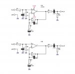
So I decided to use DC servo in preamp. I saw Damian's LM4562 preamplifier for gainclones on somewhere. Its very simple and looks goodworking one. However as you can see it uses capacitor on signal path.
I have two alternatives;
- I can use that circuit without capacitor,
- I can add a DC servo to it.
But the op-amps used for DC servo are generally expensive and low availabililty ones. I want to have my preamp very quickly, and I can find some LF411 and LF412 s in Turkey. May I use them for that project as DC servo? Because I saw that op-amps in original BPA200 project used for DC servo for LM3886s..
What do you say? May I use LF411 as DC servo for LM4562 or OPA134 (also for LT1210 in headphone amp) ? And works fine?
Thx in advance..
I am still working on a op-amp preamplifier + headphone amplifier project for my LM4702 power amp.
I have some LM4562, OPA134 and NE5534 to use that project. I dont use any capacitors on signal path in LM4702 amplifier. And also dont want to use any capacitor in preamplifier.
So I decided to use DC servo in preamp. I saw Damian's LM4562 preamplifier for gainclones on somewhere. Its very simple and looks goodworking one. However as you can see it uses capacitor on signal path.
I have two alternatives;
- I can use that circuit without capacitor,
- I can add a DC servo to it.
But the op-amps used for DC servo are generally expensive and low availabililty ones. I want to have my preamp very quickly, and I can find some LF411 and LF412 s in Turkey. May I use them for that project as DC servo? Because I saw that op-amps in original BPA200 project used for DC servo for LM3886s..
What do you say? May I use LF411 as DC servo for LM4562 or OPA134 (also for LT1210 in headphone amp) ? And works fine?
Thx in advance..
Attachments
I haven't tried using an LF411, for that. But it seems like the LF411 might be quite good, for a DC servo's opamp, since it is listed as having low offset (0.5mV max), low offset drift (10uV/degC max), and a fairly-high slew rate (10 uV/sec min). [Looking at the datasheet from http://www.national.com , it looks like the figures I quoted above are actually for the LF411A, and are slightly better than those for a plain LF411.] The LF412 looks similar, although I haven't studied either datasheet in detail.
I have a schematic and downloadable LTspice simulation of a pretty-good DC Servo circuit that I designed, at:
http://www.fullnet.com/~tomg/gooteesp.htm
That circuit should still work very well, with an LF411.
If in doubt, you could use an LF411 spice model and simulate it. And you could easily add ideal sources at the opamp inputs, to simulate the various offset voltages and currents, even including temperature effects.
- Tom Gootee
http://www.fullnet.com/~tomg/index.html
Hi,
of all the old types of opamps the LF411 is nearly ideal for DC servo duty. I think the two parameters, low offset and low offset drift, are the important ones.
There are new types that can do the job better but they are generally more expensive and often difficult to source.
Remember that the servo only NEEDS to handle frequencies below audibility. Make the servo's job easier by filtering the input signal to attenuate the audio frequencies.
Remember to also filter the output of the servo to attenuate opamp/psu noise and to attenuate the remains of the audio that passed the input filter. The servo output is usually connected directly to the inverting input and any extra signal added here will be multiplied and appear at the amplifier output.
Go and read Gootee's website for more information.
The same rules apply to a pre-amp servo as to a power amp servo. Just take care of noise injection appropriately.
Hi,
I examined the Gootee's web site.. However I am confused.
I will use 3 x gain for preamp. So for a shortcut solution;
As Damian's application for LT1201..
I want to use Damian's circuit with OPA134 instead of LT1201 and LF411 (or 412) instead of OPA604..
Do you think this is suitable for that opamps?
I am not sure, because in Spice analyse I could run this circuit with ideal op-amp sub circuits, however with OPA134 and LF411 it doesnt look like working. I dont know the reason but thats the situation.
Another way is to use MKP type caps on signal path. Do you recommend that?
Thx
Attachments
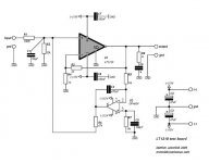
That circuit will work fine with LF411, though you'll need to capacitively couple the input. There are one or two things you should do, though. First, eliminate R7/C5 and take the noninverting input of the 411 directly to ground. Second, split R6 into two 22-27k resistors in series, then take a 100nF cap to ground from their junction.
The latter mod adds extra passive filtering of the output as Andrew suggested.
The other suggestion is to return the servo to the bottom of R2.
The latter mod adds extra passive filtering of the output as Andrew suggested.
The other suggestion is to return the servo to the bottom of R2.
Hi Ozgur,
I think there are a few issues with your last circuit.
1) I wouldn't inject the servo output into the same node where your signal goes. Look at gootee schematic how he did it.
2) If you for some reason want to keep that scheme, you can omit C5/R7 and simply ground the non-inverting input.
3) Keep an eye that you use an FET-input opamp. The LF411 is FET-input, so will work good. A more modern choice would be AD820.
4) Output filtering. You need to know what your worst case offset is. The lower (without servo) the better. If your worst possible offset is say 50mV+/- you can figure what the maximum output voltage swing of the LF411 is. Lets assume it's 13 V+/-, you have an ratio of 260:1. So you can set the voltage divider R6 : (R2||RinLT1210). Allow a safety margin and you might get by with R6 as big as 200k, which enhances filtering of the noise that is coming from your servo.
@gootee: what advantages do you see in having an active low pass filter after the integrator?
Rüdiger
darkfenriz said:No one seems to care about inputs phase reversal in DC-servo op-amps?
care to explain?
Rüdiger
Hi,
As mentioned,
I've examined the Gootee's site. However its a bit theorical... He starts from the modelling and goes with calculations.... I'm sure thats the way it should be.
However, until last month I even didnot know anything about the DC servos. Now I am still very newbie on this matter.
I dont want you to design a DC servo for me! But I want to try it, I am not sure that DC blocking cap causes any kind of bad affect on sound. But theyre very big, expensive and hard to find. So if there is a better way to solve the DC offset problem then I would make it.
Now,
I am talking what I understand:
- To connect DC servos output to the NI input directly is not a good idea.
- To use NI input of DC servo op-amp is also not a good idea.
But in Gootee's example, he uses two stages DC servo, while I coulnt understand one stage DC servo, how could I adapt it to my s h i t t y preamp project?????
More help for that poor diyer pls...
Hi Dx,
Post4 shows an inverting DC servo.
It has no filter on the input so the opamp has to amplify the whole audio and sub audio signal to extract the wanted sub-audio correction.
The circuit as shown also has no filter on the output feeding into the NI input of the amplifier. This allows any noise from the opamp/PSU to be injected into the power amp input without any attenuation.
In addition any errors that the opamp makes in extracting that sub-audio correction also get injected into the amplifier input.
Scrap that example and use one that filters both the input to the servo opamp and filters the output before injecting it back into the power amp.
Both the inverting servo and the non-inverting servo work. I believe it is easier to get the non-inverting servo to work well.
Gootee's example uses opamp2b to extract the sub-audio correction. Then opamp 2a applies active filtering to attenuate any remnants of unwanted audio and distortion and noise.
However this circuits works as a DC servo with the active filter wrapped around opamp2a removed. Then just use the passive output filter.
R8 & C4 are the input filter passing below 1Hz.
R13 & C13 are the output filter passing below 3Hz, if the second opamp is omitted. retain R1=R13.
This passive output filter allows slightly more audio through to the amplifier, but it is at a very low level and if designed correctly should be inaudible.
Hope this helps.
Hi Andrew,
don't you think R5/C4 in Post4 does the input filtering?
And output is filtered by the voltage divider consisting of R6 : R2||Rin?
If not, why?
Regards,
Rüdiger
EDIT: Meanwhile I found the other thread where gootee explains his servo. My Question regarding 'why an acitve low pass filter' is answered
Onvinyl said:@gootee: what advantages do you see in having an active low pass filter after the integrator?
Rüdiger
Hi Rudiger,
I think that probably the only advantage is better/steeper filtering, so that almost no audio frequencies can get through and get back to the amplifier input.
- Tom
Edit: Sorry. I must have been typing while your last message was posted. For others who might be interested, that other DC Servo thread is here:
http://www.diyaudio.com/forums/showthread.php?s=&threadid=103308
Dxvideo said:<snipped>
But in Gootee's example, he uses two stages DC servo, while I coulnt understand one stage DC servo, how could I adapt it to my s h i t t y preamp project?????
More help for that poor diyer pls...
Hi Dxvideo,
The "second stage" is only a lowpass filter.
You could use a simple RC passive lowpass filter, there, instead of the second opamp etc. But if you use a dual opamp, it might be worth using the other half for the filter.
For a passive RC filter, you might want to use two resistors, with a capacitor to ground between them.
- Tom Gootee
http://www.fullnet.com/~tomg/index.html
This is not quite right. In fact the servo must work extremely good up 1 kHz which isn't a problem for most opamps.AndrewT said:...
Remember that the servo only NEEDS to handle frequencies below audibility.
If you don't are convinced, do a SPICE similation in subject.
I don't think so.Onvinyl said:don't you think R5/C4 in Post4 does the input filtering?
the cap, C4, allows the opamp to work as an integrator, i.e. a constant 6db/octave slope. But there are limits to that slope.
The resistor, R5, limits the current fed into the integrator.
The non-inverting version uses the same opamp & cap combination to achieve the same slope again with limits.
no, the resistors are a dividing ladder. The cap to filter out the higher frequencies is omitted. However the cap, C2=56pF, will have a low pass filtering effect, but attenuating below 60kHz, rather than 1Hz or 2Hz.Onvinyl said:And output is filtered by the voltage divider consisting of R6 : R2||Rin?
If not, why?
Can someone enlighten us on what the relative low pass frequencies should be to obtain best performance from the dual input/output filters either side of the integrating opamp?
Should the input filter be higher or lower than the output filter?
Where in the frequency band should these filters operate to minimise the effect on the wanted audio signal?
How low is too low to make the correction too sluggish in response to output offset errors?
Hi Peranders,peranders said:
This is not quite right. In fact the servo must work extremely good up 1 kHz which isn't a problem for most opamps.
If you don't are convinced, do a SPICE similation in subject.
I can understand the requirement for the opamp to operate well at frequencies well into the audio band. Maybe much higher than 1kHz to ensure the integrator correctly creates that constant 6db slope.
However, the complete servo is only there to correct the slow drift in output offset and if working perfectly will have zero effect on the wanted audio frequencies. As is usual, there is compromise. The DC correction must be fast enough to minimise the output offset, both in extent and in time.
Yet, sufficiently filtered to avoid injecting some of the audio signal back into the amplifier.
This speed thing is what prompted my question in my previous post.
Summarising, the opamp must operate well at audio frequencies. The DC servo must pass the minimum of audio back to the amplifier correction node.
ps,
I don't need to be convinced, I am already a believer.
AndrewT said:I don't think so.
the cap, C4, allows the opamp to work as an integrator, i.e. a constant 6db/octave slope. But there are limits to that slope.
The resistor, R5, limits the current fed into the integrator.
The non-inverting version uses the same opamp & cap combination to achieve the same slope again with limits.
no, the resistors are a dividing ladder. The cap to filter out the higher frequencies is omitted. However the cap, C2=56pF, will have a low pass filtering effect, but attenuating below 60kHz, rather than 1Hz or 2Hz.
Can someone enlighten us on what the relative low pass frequencies should be to obtain best performance from the dual input/output filters either side of the integrating opamp?
Should the input filter be higher or lower than the output filter?
Where in the frequency band should these filters operate to minimise the effect on the wanted audio signal?
How low is too low to make the correction too sluggish in response to output offset errors?
Hi Andrew,
Those are good questions. (All of the rest of what I say might be wrong, but... ) I don't have all of the answers to those questions, offhand (and maybe none of the answers). But someone could just use the downloadable, ready-to-run LTspice simulation file for the DC Servo (or modify it for some other servo design) and find out, maybe by trying pre-filters with e.g. 2X and 1/2X of the post-filter's cutoff frequency.
Regarding where to put the overall cutoff frequency to minimize the effects on the audio output signal: It sure SEEMS like lower/slower would be better, in that respect. I think I tried a pre-filter for the integrator, a few years ago, but don't remember much about it, any more. It might add its own offset, though (which might be able to be compensated-for by changing the integrator's R (and C) values, IIRC).
Note that, in my DC Servo Ltspice simulation, the one that is downloadable from http://www.fullnet.com/~tomg/gooteesp.htm , one could click on the .op button and add a spice directive to calculate the THD of the amplifier output signal, such as ".four {freq} 9 20 V(OUT)" (without the quotes). Then, after a transient run, one would select Edit-->View Spice Error Log, to see the THD results. That way, it could be determined whether or not a change to the servo system had an effect on the THD of the output signal. (Note that, when using the .four command, it might be best to make sure that the transient simulation's run-time results in an integral number of signal cycles, and that the average offset is no longer changing when the last 20 cycles occur.)
Regarding what might be TOO low/slow, making the servo's correction-speed "too sluggish": I don't know that answer, either. But...
In order to not pass any audio frequencies, OR any sub-audio frequencies that would modulate the speaker-cones' centering positions (which I've read could also be "a bad thing", sound-wise), the servo system's response speed must be "very" slow. So maybe a better question would be "How fast would be too fast?". I don't know. More trade-offs, I guess.
My original design was a little faster than the current one, but also wasn't quite as stable (Faster-responding servos COULD be made more stable, but maybe only at the expense of letting more higher frequencies through.). The current version takes almost 9 seconds to fully-correct a 1-volt DC output offset of a 100 Hz 22v p-p sine output signal, but gets 90% of the way there in about 3.6 seconds. Of course, 1 whole volt of amplifier output DC offset would be quite excessive; "a lot"! That was just for testing/simulation purposes. But I think that the time-constant stays the same, basically, for any reasonable DC offest value and signal frequency.
One would hope that the only time that the SPEED of the correction would really matter would be at power-on time. And if an amplifier has excessive offset at power-on, then maybe it would be a good idea to have a delayed turn-on for the speakers, giving the servo system time to get the DC offset down by 90% or so, first.
One other possibility (remote, I hope), where response-speed might matter, and slower-yet might be better, which I have not really investigated, might be when a large "thump" of very-low-frequency signal (or maybe even just the beginning of a VLF continuous "tone") hits the output, maybe especially if the output was relatively quiet, just before that (maybe such as at the beginning of a new song?! AK!!): If the frequencies were low-enough, relative to the servo's response speed (and MAYBE also if the change in amplitude were large-enough, even for higher frequencies?!), such an event could cause a transient change in the output of the servo system, causing a transient change in the DC offset of the amplifier output. That might be able to affect the sound from the speakers, by modulating the centering locations of the speakers' drivers' magnets, and which, if it occurred, would last for the same 3.6 to 9 seconds or so, in my circuit's case. (But I don't know if the magnitude of this effect might be significant-enough to worry about, or whether or not it might be easy to make it so we wouldn't HAVE to worry about it.)
[Edit: When it's late, and I'm tired, I tend to "ramble"... ] I guess that if I were really serious about trying to make a DC servo system that would respond fast-enough to large offsets, but was as inaudible as possible in the audio band when the offset was well-controlled, I might try to use an adaptive filter (and/or maybe even integrator) design, that would lower its own time-constant when the error was larger, and raise its time-constant when the error was smaller. The time-constant could be changed using a voltage-controlled resistance. (An FET circuit could be used for that part. But I often like to use a Vactrol, which is basically just an LED encapsulated with a photocell. You could even make your own. But I've usually used something like the VTL5C2 Vactrol, which changes its photocell's resistance from a few hundred ohms to about 2 Megohms when its LED current is varied from 40 mA to 0 mA.) It might be difficult to get the response speed to be VERY much faster than we already have it, unless the error signal could be derived in a faster way; maybe dual (+/-) peak detectors (with the same type of adaptive filters...)? But at least the lowpass filtering for the LOW-error condition could be WAY-maxed-out, while still retaining "at least" the existing response speed for larger-error conditions. (It CAN work very well: I used a similar technique for an adaptive filter for the output of a peak detector that was part of a feedback system that controlled the output amplitude of periodic signals in an LM1875-based audio-frequency amplifier in a measurement instrument, and was able to get the peak detector's output to slew up OR DOWN very quickly, when the amplitude was far from the desired level, such that I could make a 5v P-P input result in any desired output amplitude from 30V P-P to 1V P-P, stable within less than 200 ms, for any frequency from 60 Hz to 20 kHz, but was still able to get a ripple voltage of well-under 1 mV P-P at the peak detector's output once the error became small, even for 60 Hz sawtooth waveforms.)
Sorry to have blathered-on about all of that, for so long.
- Tom Gootee
http://www.fullnet.com/~tomg/index.html
that sounds like support for the philosophy that the output offset should be minimised BEFORE activating the DC servo.gootee said:...........Regarding what might be TOO low/slow, making the servo's correction-speed "too sluggish": ............. But.............One would hope that the only time that the SPEED of the correction would really matter would be at power-on time. And if an amplifier has excessive offset at power-on, then maybe it would be a good idea to have a delayed turn-on for the speakers, giving the servo system time to get the DC offset down by 90% or so, first..............
The question that follows is:-
would it be better to minimise offset at completely cold and let the DC servo zero out the warm up offset?
or
set the warmed up offset to zero and hope that the first turn on offset is low enough and short enough to be tolerable.
I prefer the first alternative.
But, what if one switches on a pre-warmed amplifier?
- Status
- This old topic is closed. If you want to reopen this topic, contact a moderator using the "Report Post" button.
- Home
- Amplifiers
- Chip Amps
- DC Servo question...