Hi,
First of all, I am a complete noob when it comes to electronics. I know how to solder and connect few things but that's about it.
I have build my first chip amp based on Brian's Rev C LM3875 kit. It is stereo version that is powered by CT trafo. It has one power supply board and two channel boards.
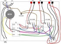
Could somebody here check the connections I have drawn on the image (attachment) and let me know if I did it correctly? My trafo is CT 21V-0-21V, I have a fuse, 10K volume pot and power switch. Connections for the CT are according to this post:
http://www.diyaudio.com/forums/showthread.php?postid=887047#post887047
I also have one additional question. My volume pot just has 6 connections (2 rows of 3 connections). I know that it is one row per channel, but how do I know which one is IN, OUT and GND? The pot has the following information on it:
AB 719110-60
10K-OHM+-10%
TYPE J
MEXICO
Thank you.
p.s. Please go easy on me if there is something really bad in the attachment, because like I stated before, I do not have a lot of knowledge about electronics. That is why I picked a kit and did not attempt to build an amp from scratch.
First of all, I am a complete noob when it comes to electronics. I know how to solder and connect few things but that's about it.
I have build my first chip amp based on Brian's Rev C LM3875 kit. It is stereo version that is powered by CT trafo. It has one power supply board and two channel boards.
Could somebody here check the connections I have drawn on the image (attachment) and let me know if I did it correctly? My trafo is CT 21V-0-21V, I have a fuse, 10K volume pot and power switch. Connections for the CT are according to this post:
http://www.diyaudio.com/forums/showthread.php?postid=887047#post887047
I also have one additional question. My volume pot just has 6 connections (2 rows of 3 connections). I know that it is one row per channel, but how do I know which one is IN, OUT and GND? The pot has the following information on it:
AB 719110-60
10K-OHM+-10%
TYPE J
MEXICO
Thank you.
p.s. Please go easy on me if there is something really bad in the attachment, because like I stated before, I do not have a lot of knowledge about electronics. That is why I picked a kit and did not attempt to build an amp from scratch.
Attachments
Hi,
I am working through your diagram so this may not be my last.
The safety earth from input socket to chassis MUST BE PERMANENT.
Do not share a single bolted fixing with the audio ground.
You can add an extra nut above the permanent safety earthing nut. But, it's usually easier to put the safety earth very near the input socket.
The PG+ and PG- look like duplicate grounds running between your amplifier and PSU.
Are the PG+ and PG- connected at the PSU?
Are the PG+ and PG- connected at the amplifiers?
If so then connecting them with two wires will create a loop. This might have no effect, but worth avoiding.
Is AC2 connected to the correct tab?
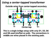
Where are your diodes and shorting links for a centre tapped transformer?
A little hint that may save some grief.
build up one channel only putting all your items in their final locations. Omit the amp to PSU connections for your first mains test.
Plug in the mains via a mains test bulb, NOT direct. It could avoid an explosive blow up if you have inadvertently mis-wired something.
Check your PSU voltages are correct value and that the capacitor voltage rating are not exceeded. Check the polarity of the PSU outputs.
When all in the PSU is OK, then connect amp to PSU and AGAIN plug in via that test bulb. Use the test bulb EVERY time you modify anything in the amplifier assembly.
I am working through your diagram so this may not be my last.
The safety earth from input socket to chassis MUST BE PERMANENT.
Do not share a single bolted fixing with the audio ground.
You can add an extra nut above the permanent safety earthing nut. But, it's usually easier to put the safety earth very near the input socket.
The PG+ and PG- look like duplicate grounds running between your amplifier and PSU.
Are the PG+ and PG- connected at the PSU?
Are the PG+ and PG- connected at the amplifiers?
If so then connecting them with two wires will create a loop. This might have no effect, but worth avoiding.
Is AC2 connected to the correct tab?
Where are your diodes and shorting links for a centre tapped transformer?
A little hint that may save some grief.
build up one channel only putting all your items in their final locations. Omit the amp to PSU connections for your first mains test.
Plug in the mains via a mains test bulb, NOT direct. It could avoid an explosive blow up if you have inadvertently mis-wired something.
Check your PSU voltages are correct value and that the capacitor voltage rating are not exceeded. Check the polarity of the PSU outputs.
When all in the PSU is OK, then connect amp to PSU and AGAIN plug in via that test bulb. Use the test bulb EVERY time you modify anything in the amplifier assembly.
AndrewT,
Thank you for reviewing my connection. I really appreciate it.
Attached schematics will answer probably all of your questions regarding PSU as this is what used to built mine.
Q: Are the PG+ and PG- connected at the amplifiers?
I can't really tell. From the Brian's PDF it looks like PG+ is connected to the - of the big capacitor mounted on the board, but I might be mistaken (PG- to the + of the big capacitor). The amplifier board is build according the the instructions located here:
http://www.chipamp.com/nigc_kit-users_guide.pdf
I have used all parts specified in the PDF (there are no empty soldering spots on the board).
Thanks again.
Thank you for reviewing my connection. I really appreciate it.
Attached schematics will answer probably all of your questions regarding PSU as this is what used to built mine.
Q: Are the PG+ and PG- connected at the amplifiers?
I can't really tell. From the Brian's PDF it looks like PG+ is connected to the - of the big capacitor mounted on the board, but I might be mistaken (PG- to the + of the big capacitor). The amplifier board is build according the the instructions located here:
http://www.chipamp.com/nigc_kit-users_guide.pdf
I have used all parts specified in the PDF (there are no empty soldering spots on the board).
Could you explain that to me? I really have little to none experience with electronics and have no idea what permanent safety earth is.The safety earth from input socket to chassis MUST BE PERMANENT.
Do not share a single bolted fixing with the audio ground.
Thanks again.
Attachments
Hi,
have another look at that PSU PCB.
The link across the middle joining the empty holes for d7 & d8 joins PG+ to PG-.
Now go and check your amp PCB and see if PG+ is joined to PG-.
Note also that for a centre tapped transformer only 4 diodes are fitted and 4 are left empty.
Add the three links to join the positive half to the negative half.
Hi,
the Safety Earth is the third wire in your mains cable.
It is there to prevent users being killed by faulty equipment.
It must be permanently connected to any and all exposed conductive parts of your equipment.
This is the bolted or welded connection that the third "earth" wire makes to your chassis. Note soldered is NOT an option.
The Safety Earth is there to keep the chassis at a lowish voltage until the fuse ruptures due to a mains fault. This connection must allways be present, particularly while you are mucking about inside a live amplifier.
Oh, I never do that!
Just wait till you have to measure voltages trying to find out why it doesn't work!!!!
You do not want to have to dismantle the Safety Earth to remove the audio ground wires. That's why they should never share the same fixing.
I have checked the amp PCB and it looks like PG- is joined with PG+ (together with OG, SG and CHG).Now go and check your amp PCB and see if PG+ is joined to PG-.
That is exactly how my PSU is built.Note also that for a centre tapped transformer only 4 diodes are fitted and 4 are left empty.
Add the three links to join the positive half to the negative half.
I will remove the connection between PG- on the PSU going to PG- on the amp PCB (pink line on my schematics). I will also add a separate bolted safety ground near the input socket (thanks for your detailed explanation) and test the whole thing with bulb.
Any idea how to test the POT to determine which pin is in, which is out and which is ground?
Thanks for all your help.
Hi,maurycy said:Any idea how to test the POT to determine which pin is in, which is out and which is ground?
turn fully off (anti-clockwise) and measure from middle to end. The end that reads zero ohms is the common side of the pot.
I saw in your wiring diagram that the ground follows the route of the line in.
This may not give the quietest residual noise.
It might be quieter to ground the RCAs direct to the audio ground and just connect the screen at the RCA end. Or maybe connect screen at both ends on the first leg RCA to POT, but then ground the second leg only at the pot end. There are numerous combinations here, but be careful that when the deliberate ground is disconnected it should measure isolated from the audio ground. It's worth checking this to ensure you have not wired in a ground loop.
- Status
- This old topic is closed. If you want to reopen this topic, contact a moderator using the "Report Post" button.
- Home
- Amplifiers
- Chip Amps
- Noob building first amp: please check my connections