Help me constracting my home theater
I am constructing a 5.1 ch home theater. I considered two TDA2616 (2*12W RMS) for front and rear, TDA2050 (24-35W RMS) for subwoofer and another TDA2616 (I'd use only one channel) for the center.
I decieded to use a 15-0-15 transformer which will supply +-15V.
Now say, the amperege of the transformer should be taken???
is there any no way to adding S/PDIF input and remote control???
Any suggestion will be greately appriciated...
Hi,
Its impossible to decode AC3 coded digital signals without Dolby Laboratories licence. So you cannot add a 5+1 output digital input to your system.
For remote controlling, diyclub.biz has some input selector and volume control units with IR remote controls. You can buy one of them. Theyre cheap and work fine.
And concerning the trafo issue: my suggestion is, use one 150W 2 x 15v trafo for just TDA2050 (use two TDA2050 as bridged) and one 150W for the other channels. They look you some overdose but you will need this much power if you consider moives sound tracks have very high dynamics and if you use lower wattage trafos then high volume effects will be clipped.
Thanks Thanks and thanks...
If their are any option to add a LCD display which will display the volume level and some others, give me the circuit diagram please....
And what's your suggestion for the center speaker amplifier?
Ohoo, I forget to say, diyclub.diz says they ship All orders to France, Italy and Germany only . I live in India ..What I do??
No, no...
I am living in Turkey and I have one RC kit from there.. Theyre very fast on shipping.
And for the centre channel: You may use one 2616 in bridge mode also. Because you will need more power for the center.
For LCD display option, I dont have any idea, however there is a "WM Stamp" topic in this forum. If you search, you will find it. May be you can use that with three WM8816 chips...
A last note, If available in India, I think you can use LM1876 for all channels, I use them for many projects, and I can say theyre the best chipamps for that power range.. You may use one (in bridged) for subwoofer and you can get 50W, two for front and rear channel that you can get 25W per ch. and one for center. You will spend only four chips and two sperated power supply...
I can also give you a very good active subwoofer filter schematics if you want.
Hmm..
Theorically you CANNOT make a subwoofer enclosure without some calculations.
However to make this calculations you will need thiele small parameters of the subwoofer driver you use. And now you dont have.
So if you need a subwoofer that means you need deep and powerfull basses. My recommendation is; (I know a lot of diyers will have objections to this)
You may use a 20cm 8ohm no name cheap subwoofer (possibly China made), put it to a 30lt (inside dimension) box and put an adjustable 70mm port to it.
And use that circuit as bass boosted preamp + LPF;
An externally hosted image should be here but it was not working when we last tested it.
Hi Dx,
does ic1a operate correctly?
What is the output offset in your built circuit?
The only route that I can see for the input offset current is via the leakage of the DC blocking capacitor.
It is normal for a filter of that type to be fed from a near zero impedance.
Before the first filter 10K, r11, you have a cap and it's impedance is far from zero as soon as the signal becomes anything other than infinite frequency.
Dear Andrew,
I use that design for a friend. And now he's very happy with it.
Its a simple desing as you already noticed. A low pass filter and a linkwitz feedback bass boosted preamp.
I connected the second stage to the first with DC couplage. However the second stage has a low frequency limit via C5 and its about 7Hz... Now if you consider our power stage will have a DC blockage cap. before the IC amp then there will be no offset (theorically) on spaker output.
In real life, What I measured on IC1B s output is exaclty 0mV... But I've never meaused IC1As output. May be it has a little offset. I will measure it soon.
However I coulnt understand
"Before the first filter 10K, r11, you have a cap and it's impedance is far from zero as soon as the signal becomes anything other than infinite frequency."
What you mean? Should I remove the 10u?
And for your "bridge mode" warning. He will use +/- 18v PSU and will drive a 8ohm load with it. Single LM1876 can drive 4 ohm loads with +/-20v PSU. So we will have 4v headroom with bridge mode 8 ohm driving. I think there will be not a problem. I've tried that with +/-22v PSU and SOAR protection never activated.
Hi Dx,
maybe the input offset current is so low that it all leaks past the 10uF.
The first filter will not achieve correct filter response with a high source impedance. Removing the blocking cap hardly helps that due to the non zero impedance before it.
A summer to get the mono bass signal should normally use an inverting summer circuit and the two summer resistors r1 & r8 form the gain setting as well. Then that first opamp feeds straight into the high pass filter. That way the filter sees the Zout of the inverting opamp and the inverting opamp does the adding.
An alternative is to adopt an MFB filter for that first high pass. This is inverting and can be preceeded with two inputs that add to give a mono signal and these inputs also serve to define the gain of the filter. The MFB saves an opamp to give the summer and filter rolled into one stage.
Can you simulate what you have built and compare it to a zero source impedance immediately before r11?
I'd use 6'' subwoofer.
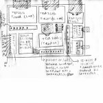
I included the rough sketch of my main amp board plan.
I deciede to construct the amplifiers on seperate vero board and finally mount them on a cardboard. and i'd place the cardboard in the subwoofer box. i'd make another box to place the two transformer...
Now tell me, the fuse ratings should be given for 2*TDA2616 and TDA2050(30W RMS) and TDA2040(20W).
Also give me suggestions and any design faults or upgrade plan if you find..
Thanks...
....Paswa
 for a while. Next week I'll write you again.
I'm coming back
I was busy during my exam...
Now please tell me using 3'' 8 ohm speakers for front and rear and 4'' aohm for centre and 6'' subwoofer will be sufficient or not?
Tell be about bass reflex subwoofer enclouser....how to construct it...or any other type of good enclouser...because I need more more bassssss...
If there would be any noise or any other issue if a put the power transformers near to the main amplifier system??????
Please help.....thankkkk....u..
Re: I'm coming back
that information is so useless, I doubt anyone can give you a sensible answer.Paswa said:I was busy during my exam...
Now please tell me using 3'' 8 ohm speakers for front and rear and 4'' aohm for centre and 6'' subwoofer will be sufficient or not?
Tell be about bass reflex subwoofer enclouser....how to construct it...or any other type of good enclouser...because I need more more bassssss...
If there would be any noise or any other issue if a put the power transformers near to the main amplifier system??????
Please help.....thankkkk....u..
- Status
- This old topic is closed. If you want to reopen this topic, contact a moderator using the "Report Post" button.
- Home
- Amplifiers
- Chip Amps
- Help me construct my home theater