Hello,
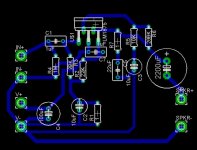
I am quite a newbie to higher powered amps. I have built a small ~6 watt amp and a couple of headphone amps, but this will be my highest powered amp and first one with a custom board. I did my best to make a star ground and make separate paths for the feedback, input, and load grounds. The board is for a LM1875 running in single supply mode. I will use a power supply from a busted printer for this design. It is 30V @ 1 amp. Is this a suitable sized power supply to power two LM1875's? A picture of my board design is attached. Does the design look good enough?
Thanks,
Robert S.
Attachments
Hi Robert,
I am by no means an expert, but I have two suggestions:
- The LM1875 should be right at the edge of the board, so it can be easily attached to a heatsink.
- The feedback resistor (R6 on your PCB) should be very close to the pins of the LM1875, to form the shortest possible feedback loop.
Good luck,
Anton
I will use a power supply from a busted printer for this design. It is 30V @ 1 amp. Is this a suitable sized power supply to power two LM1875's? A picture of my board design is attached. Does the design look good enough?
Hello.. No way I'd use just 1A current suply. Not even for one chip. Further more, I'd go for dual suply mode. This way I avoid the output cap.
I''ve used this chip and it's very good indeed; very musical, better than the TDA7294 for example.
edit: the powe traces are to thin and I subscribe to the above coments.
Best luck!
LM1875 is good choice. I used that chip for a PC active speaker system 10 years ago. Theyre still working in my friends room.
Anyway, I think;
- The PCB may be smaller size. This will reduce the noise.
- Negative feedback line must be shorter. Long NFB line is the main cause of possible oscillations.
- Power lines must be thicker as possible. They carry a lot of current.
- Its better to use a split power supply. In this case you may save some components and you can ommit the output capacitor. Thus will reduce the distortion, gives a large frequency response and a flat phase response!
- You should take consider on heatsinking. With this configuration; its too hard to attach a enough heatsink. You must move the IC to the corner of PCB..
Thats all, for now.
Thank you all for your input. I redesigned the board for a split power supply. The chip is placed fine for the heatsink that I am using. For two of these boards, each putting out 15 Watts MAX, what size transformer should I get? Also, what would be the ideal voltage to aim for? I attached the new design for the board.
Attachments
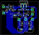
Thats better. But you must make the V+ line bolder. And do the same thing for the speaker line.
Another issue is on GND line. You must collect all GNDs to one point. As I see the GND is not ringing but some long. You can reduce the lenght and make a star gnd point.
And you can move colser the 0,1uF filtering caps to IC s power pins.
For the transformer question;
You will need +/-20v for 15W @ 8ohm. If you use 8ohm speakers then 15 - 0 - 15v secondary and 75VA rated transformer will be enough for two channel.
However if you will use single power supply for both channel, I afraid you will have a gorund loop problem. Because you will get both power gnd and signal gnd for each PCB. So theyre going to the same point anyway. My suggestion is; you may make a combined PCB for two channel amp with one GND point then connect it to a single power supply.
If you need more information pls dont hesitate to ask.
He should make a foil path for the input ground that will be connected directly to ground... am I right?
AndrewT said:re post5 layout.
The Zobel is sharing a ground return with the input components = disaster.
Almost.rhavecilla said:He should make a foil path for the input ground that will be connected directly to ground... am I right?
Better to disconnect the Zobel capacitor from the input/signal ground and move the cap to the speaker return trace. They are right next to each other.
Next, the signal ground passes through the noisiest track on the PCB. The trace between the four decoupling caps is full of half wave current spikes. Do not pass the signal ground through this area. Try to find a route that goes straight to the main power ground in the middle of the PCB.
Bob0513 said:Hello,
I am quite a newbie to higher powered amps. I have built a small ~6 watt amp and a couple of headphone amps, but this will be my highest powered amp and first one with a custom board. I did my best to make a star ground and make separate paths for the feedback, input, and load grounds. The board is for a LM1875 running in single supply mode. I will use a power supply from a busted printer for this design. It is 30V @ 1 amp. Is this a suitable sized power supply to power two LM1875's? A picture of my board design is attached. Does the design look good enough?
Thanks,
Robert S.
I have some LM1875 pcbs if you want one. Drop me an e-mail and I will send you a set for you to try out.
If anyone else wants one, drop me a mail, as I have 5 sets sitting on my desk that I can send out for free.
--
Brian
- Status
- This old topic is closed. If you want to reopen this topic, contact a moderator using the "Report Post" button.
- Home
- Amplifiers
- Chip Amps
- LM1875 design, help a newbie out