Hi all,
I'm looking to replace noisy VCAs on a circuit board with a PGA4311/ two 2311 or a 2320. For testing, I have 2320 samples since I don't want to work on a 6V to 5V PSU right now.
The question is, TI states that the PGAx3xx should see 600ohm on it's input. I have this sample & hold circuit feeding the current VCAs. Is there something to change to make it look like 600 ohm?
I'm not sure of the capacitor value and I have not put it in the schematic for this reason.
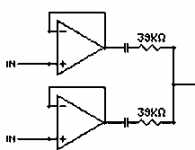
The schematic included is for one of the four channels that are controlled by VCAs. Each channels have two opamps from two different sources.
I'm looking to replace noisy VCAs on a circuit board with a PGA4311/ two 2311 or a 2320. For testing, I have 2320 samples since I don't want to work on a 6V to 5V PSU right now.
The question is, TI states that the PGAx3xx should see 600ohm on it's input. I have this sample & hold circuit feeding the current VCAs. Is there something to change to make it look like 600 ohm?
I'm not sure of the capacitor value and I have not put it in the schematic for this reason.
The schematic included is for one of the four channels that are controlled by VCAs. Each channels have two opamps from two different sources.
Attachments
Hi,
PGA4311 Datasheet reads (pg.7): "For optimal performance, it is best to drive the PGA4311 with a low source impedance. A source impedance of 600 ohms or less is recommended. Source impedances up to 2kohms will cause minimal degradation of THD+N. Please refer to the “THD+N vs Source Impedance” plot in the Typical Characteristics section of the datasheet."
With your circuit you have ~20kohms source impedance (39k//39k). Looks like way too high to get low THD and to drive the input ladder network correctly (Zin is 10kohms//3pF, with 20k Zsource you'll loose 9.5dB and maybe some channel matching also). You might want to use a (op-amp) follower after your mixer circuit (that's what it looks like to me), or do the mixing ahead of the opamp. If your op amps can afford the cross current you could also decrease the resistors to ~4k and then select the caps to give the low-freq. roll-off as required, per C=1/(2*Pi*f*R)
Regards, Klaus
OK, so a second buffer or 8 VCAs would be necessary if I understand, otherwise the feedback loops might freak out if they blend both signals between each others too much?
I'm not sure if I can mix the signals before the opamps. Will the 4053 logic analog switches feeding the S&H circuits like it or not?
I'm not sure if I can mix the signals before the opamps. Will the 4053 logic analog switches feeding the S&H circuits like it or not?
Um.. not knowing the exact schematic/application this is hard to tell. I would go for seperate op-amp buffers in front of the PGAs (those ain't VCAs, btw) so you can leave your circuit as it is. That makes 4 op-amps in total whichs seems not to be too much effort to incorporate in the circuit, using a quad device e.g.
The PGAs and the VCAs do pretty much the same job anyways...
I'll copy paste from an other forum what the D/A stage is :
1-There are two mono 16-bit 333kHz max DACs,
2-They are demuxed into 4 channels each with 4053,
3-Then there's the Sample & Hold circuit,
4-Then the 8 channels are combined in pairs, making four channels,
5-Then this signal is sent to the VCAs,
6-And then to an inverting buffer,
7-To finally get to the output.
There are only quad opamps in there.
There's a mono output containing the four channels and an headphones output too. This one uses even more opamps. (After the last stage, it parallels the four signals with 100kOhm resistors together to pass through an other inverting buffer)
It's quite hard to explain the whole thing since this part of the circuit is a little too complex for nothing.
PM me for the schematic.
Hi DragonMaster,
This is easy. Using the right tool for the job. Install a buffer between your circuits. Any op amp capable of driving a 600 R line will work as well set up for unity gain. Make sure the op amp is stable into unity gain. So, 5532's will work, 5534's will need extra compensation (use a different part then).
Believe me when I say that it may hiss also if the source impedance is too high.
-Chris
Believe me when I say that it may hiss also if the source impedance is too high.
Now here we have something really interesting. The problem with the actual circuit is that it hisses a lot.
After the VCAs that are in there right now, there's an inverting buffer.
How about using an inverting buffer between the S&H circuit and the PGA? There are inverting buffers situated after the VCAs right now, and the PGAs have a buffered output. I could skip the last inverting stage that way, this would make one less opamp in the signal path.
Hi Antoine,
-Chris
Give that a try.How about using an inverting buffer between the S&H circuit and the PGA?
-Chris
OK, I found how to make an inverting buffer here:
http://hyperphysics.phy-astr.gsu.edu/hbase/electronic/opampvar.html#c2
I suppose that the 39kOhms in parallel can act as R1, so I can leave out R1 and put a 19kOhm Rf, right?
Also, to make the buffer's output 600 ohm, I just put a 600ohm resistor in series with the output, right?
http://hyperphysics.phy-astr.gsu.edu/hbase/electronic/opampvar.html#c2
I suppose that the 39kOhms in parallel can act as R1, so I can leave out R1 and put a 19kOhm Rf, right?
Also, to make the buffer's output 600 ohm, I just put a 600ohm resistor in series with the output, right?
Hi Antoine,
-Chris
For this to be an inverting buffer, R1 = Rf. Otherwise you will have gain. R1 also determines the input impedance as the input terminals are forced to be the same instantaneous voltage. That is why the inverting input is called a virtual ground when the non-inverting input is referenced to ground or some common AC reference point (As in a single supply version).I suppose that the 39kOhms in parallel can act as R1, so I can leave out R1 and put a 19kOhm Rf, right?
-Chris
OK.
Oops, I meant a 19.5kOhm resistor, not 19kOhm.
Now about power rails, will powering the inverting buffers with ±5V cause problems since the S&H circuit uses ±6V?
I would personally feed the inv.buffer + PGA circuit with ±5V using a LM2941/2991 combo fed from the not-so-well filtered ±6V lines already available. The PICmicro and digital section of the PGA could use the digital voltage 5V line. I'm trying to go cheap as I might have to build this circuit for a few persons which might not want to spend lots of money on it.
")
Well, there currently are two voltage followers with a 39kOhm output impedance in parallel. To match this, I use an Rf with half the value?
Oh, I see what you mean, I think... I'm trying to make the buffer's output 600 ohm to reduce noise and THD at the PGA level, but the buffer seeing an high impedance output actually causes noise too.
Oh, I see what you mean, I think... I'm trying to make the buffer's output 600 ohm to reduce noise and THD at the PGA level, but the buffer seeing an high impedance output actually causes noise too.
Hi Antoine,
Why not reduce those mixing resistors and run the entire thing at a lower impedance? Your numbers are correct. The only thing to watch for is loading down your inverting buffer with the feedback network.
There will be give and take, so try for 10K total and use 20 K resistors for your mixing section. Normally for current sharing I would go lower still. You could then use a 10K dip resistor where the tracking will be very good.
-Chris
Hey, old topics...
I had an idea a few weeks ago that would solve the PGA input impedance vs. feedback problem : I could simply use two PGA4311s instead, and mix the signal pairs after them rather than adding an other stage, would that work and be a better solution than working on feedback resistors?
I had an idea a few weeks ago that would solve the PGA input impedance vs. feedback problem : I could simply use two PGA4311s instead, and mix the signal pairs after them rather than adding an other stage, would that work and be a better solution than working on feedback resistors?
- Status
- This old topic is closed. If you want to reopen this topic, contact a moderator using the "Report Post" button.
- Home
- Amplifiers
- Chip Amps
- PGA4311 600ohm input source impedance