Hi,
I am trying to follow the instructions posted by eddog in one of the threads about mounting CT to Brian's Rev C power supply board:
"Only four diodes should be mounted to the rev 3 power supply board, these are D8,D4,D5 and D1. Run a jumper from D6(outside hole) to D7(outside hole). Then run a jumperfrom D2(outside hole) to D3(outside hole). Also run a jumper from D2(inside hole) to D3(inside hole). Your centertapped transformer connects as such(on my working amp anyway), Your centertap wire goes to PG-(yes that is correct), your V- goes to AC2(inside) and your V+ goes to AC2(outside). You now have a working rev 3 amp."
I have the 42V CT transformer and power supply board with only 4 diodes. My transformer is this one: http://www.apexjr.com/miscellaneous.html#Toroids (6th on the list). It gives me 21-0-21. And here is where I am confused. Eddog mentioned V- and V+ but I do not know how do I determine which 21V is + and which one is - ?
Any help is appreciated.
Thanks.
Hi,
the 21-0-21 is AC. They do not have a +ve or a -ve.
You have already identified the centre tap and where it goes.
Now connect one 21Vac to AC2 and the other 21Vac to the second AC2.
The rectifiers then direct the current to give you +ve and -ve outputs.
BUT
do check the PSU voltages BEFORE you connect the amplifiers.
AND
do use a light bulb to power up the PSU the first time and EVERY time you add or modify something in the assembly.
Hi,
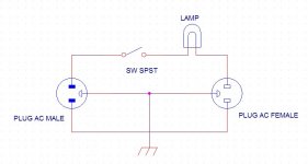
Thanks to Speed for the new diagram.
The male plugs into the mains wall socket outlet.
The new equipment plugs into the female socket outlet.
The wiring applies to UK as well. Just the colours are different from the US.
You don't need the switches, the bulb tester works properly without any switches.
Any added switches simply make the tester more usable.
Check here for a very thorough description of the set-up and testing process : Building a Gainclone chip amp power supply.
Follow that and you won't go wrong.
Follow that and you won't go wrong.
but the guy/gal does want to do his own research. He justs wants answers!Follow that and you won't go wrong.
- Status
- This old topic is closed. If you want to reopen this topic, contact a moderator using the "Report Post" button.
- Home
- Amplifiers
- Chip Amps
- Question about CT transformer and Brian's Rev C power supply board