A rotery encoder controlled integrated chip amp LM3875
I am trying to come up with a pcb design for a very compact integrated amp based on the LM3875 chip, I have posted a couple of threads already.
My basic premise is that the whole amp will fit in a hammond 1455 case 220mm*100mm*55mm. That is pretty small when you consider I wish to use a regulated power supply.
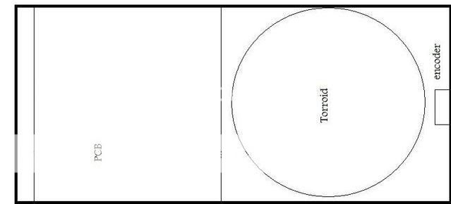
I had looked before at using Pedja Rogic's Buffer. However the problem of volume control becomes an issue. The torroid really needs to be at the front of the case. That way signalling in and out is as far as possible from it.
If I use a stereo pot, then the signal wires must pass very close.
A digital volume pot seems the easiest solution. I have a DS1802, and I certainly could use it. However on searching the Maxim site, I noticed the MAX5440.
Call it silly, but the idea of an encoder controlled volume pot seems good. The added advantage of a 5 LED readout kinda got me interested. The chip also includes buffers at the wiper out stages, which makes me think it would suit an Inverted amp. So I thought I would give a try at designing one.
So far I have sketched out the schematic on Dip trace. I would appreciate comments.
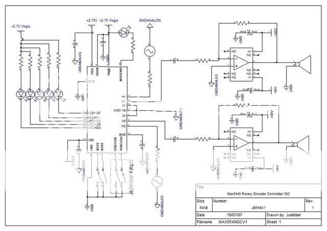
The caps obviously are wrong in the schematic, I will of course be using bipolar caps in the signal paths, bias to ground etc.
I opted for using dual +/-2.75V suplies for the chip. It will allow single voltage operation, but the datasheet indicates higher levels of THD+N in this configeration. I have also opted to bypass the -V supply to ground.
I have included a resitor between the source and the chip. This is to bring down the value of the peak voltage to within the tolerances of the chip (Vmax 2.75v peak) as my calculations say that the max rms the chip can handle is roughly 1.9vrms.
Maxims datasheet and description
Essentially I see this as being a similay implementation to the way Pedja ran the DS1802, but with a differnt chip.
I have yet to decide the values for the rest of the components, I will aim to have pretty high gain on the lm3875 to counter the lower input voltage.
I am also concerned by the datasheet. It shows the frequency response of the chip tailing sharply at 100khz is this too low?
Your comment please. Try not to be too negative about the choice of chip. I know it's only got 32 wiper positions etc
I am trying to come up with a pcb design for a very compact integrated amp based on the LM3875 chip, I have posted a couple of threads already.
My basic premise is that the whole amp will fit in a hammond 1455 case 220mm*100mm*55mm. That is pretty small when you consider I wish to use a regulated power supply.
I had looked before at using Pedja Rogic's Buffer. However the problem of volume control becomes an issue. The torroid really needs to be at the front of the case. That way signalling in and out is as far as possible from it.
If I use a stereo pot, then the signal wires must pass very close.
A digital volume pot seems the easiest solution. I have a DS1802, and I certainly could use it. However on searching the Maxim site, I noticed the MAX5440.
Call it silly, but the idea of an encoder controlled volume pot seems good. The added advantage of a 5 LED readout kinda got me interested. The chip also includes buffers at the wiper out stages, which makes me think it would suit an Inverted amp. So I thought I would give a try at designing one.
So far I have sketched out the schematic on Dip trace. I would appreciate comments.
The caps obviously are wrong in the schematic, I will of course be using bipolar caps in the signal paths, bias to ground etc.
I opted for using dual +/-2.75V suplies for the chip. It will allow single voltage operation, but the datasheet indicates higher levels of THD+N in this configeration. I have also opted to bypass the -V supply to ground.
I have included a resitor between the source and the chip. This is to bring down the value of the peak voltage to within the tolerances of the chip (Vmax 2.75v peak) as my calculations say that the max rms the chip can handle is roughly 1.9vrms.
Maxims datasheet and description
Essentially I see this as being a similay implementation to the way Pedja ran the DS1802, but with a differnt chip.
I have yet to decide the values for the rest of the components, I will aim to have pretty high gain on the lm3875 to counter the lower input voltage.
I am also concerned by the datasheet. It shows the frequency response of the chip tailing sharply at 100khz is this too low?
Your comment please. Try not to be too negative about the choice of chip. I know it's only got 32 wiper positions etc
Silence was the loud reply...
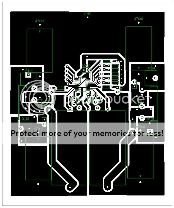
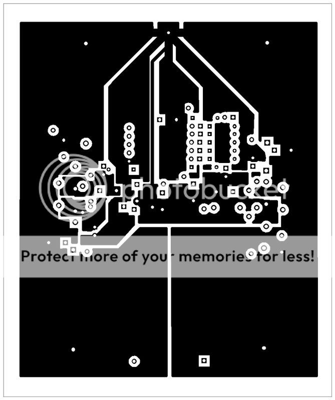
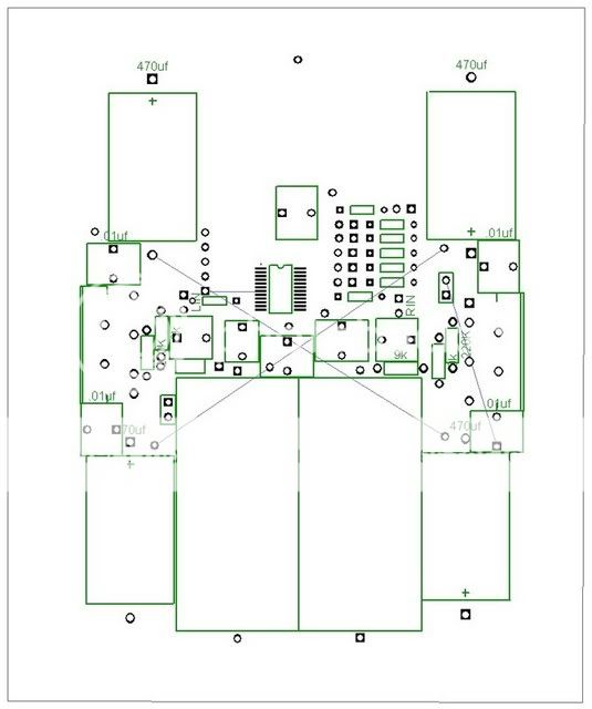
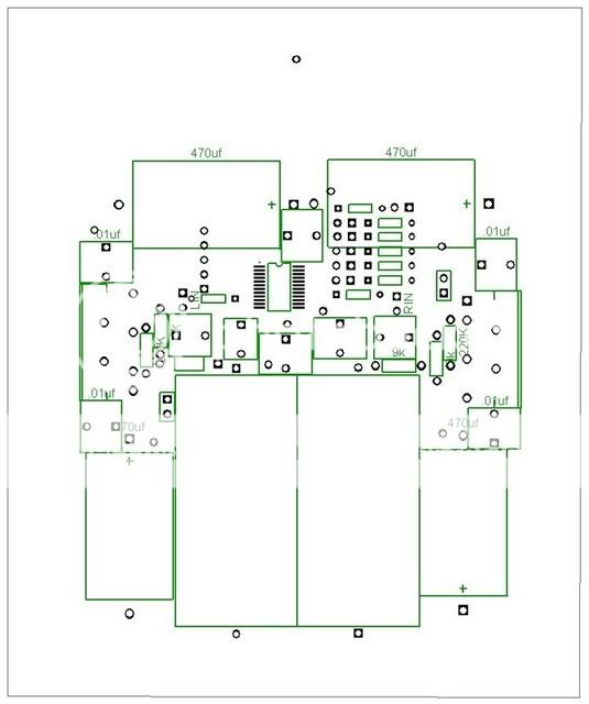
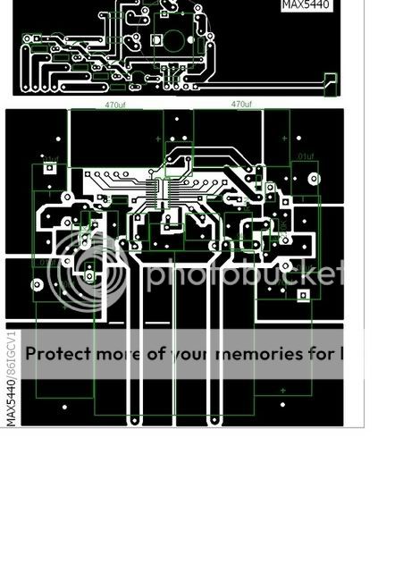
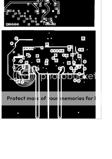
I have been busy putting together a pcb for the above schematic. Here it is
Top
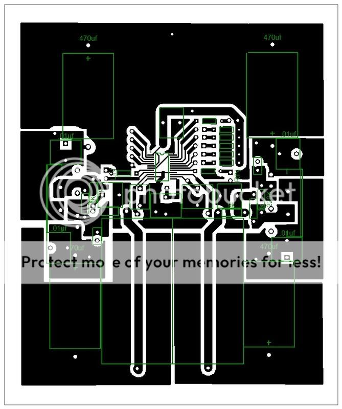
Bottom

I have been reading the datasheets and MAxim have another chip the MAX 5480 which is a push button version of the 5440. My design is such that if I widen the solder pads, either chip should be compatible. The 5480 requiring a trace to be cut.
There is still some tidying up to do.
I have to produce a second board for power supplies as well. The aim is that the boards will stack.
Comments please. I hope to get the boards etched this week. So if I have made a horrible mistake, it would be good to know this weekend.
Thanks in advance
Blair
ps if theere are any diptrace users out there. I am having trouble getting the traces to align with the pads of the chip. I have decreased the gridlines to their lowest setting. What have I missed?
I have been busy putting together a pcb for the above schematic. Here it is
Top
Bottom
I have been reading the datasheets and MAxim have another chip the MAX 5480 which is a push button version of the 5440. My design is such that if I widen the solder pads, either chip should be compatible. The 5480 requiring a trace to be cut.
There is still some tidying up to do.
I have to produce a second board for power supplies as well. The aim is that the boards will stack.
Comments please. I hope to get the boards etched this week. So if I have made a horrible mistake, it would be good to know this weekend.
Thanks in advance
Blair
ps if theere are any diptrace users out there. I am having trouble getting the traces to align with the pads of the chip. I have decreased the gridlines to their lowest setting. What have I missed?
I am going to bed now after a marathon19 hour session in front of the PC.....
I have updated my design to include a low pass filter before the LM3875, I aim to add a slope off at around 20Khz. I wont need to worry about the chip at higher frequencies as the max5440 filters frequencies above 100Khz quite sharply.
Have narrowed the width taken up by the components to allow more heatsink, and have put together the bulk of a schematic for a regulated power supply.
I solved the issue of the uneven tracks on the chip's pads, discovered some issues with ground loops and resolved them and picked, designed (in pattern editor) the sizes for all of my caps. I just have to place 2 of the filter caps. I'll do this tomorrow morning.
I haven't decided yet on all the resitor values, this is where I could do with some help.
I also have some questions...
- Is my idea to place a resistor in series with the input of the pot going to reduce the voltage correctly? Value wise the pot is 40K so a 40K resistor would halve the voltage at the pot?
- What is a typical RMS voltage from a source. The GF currently is taking sound from a soundblaster live 24bit soundcard. What sort of attenuation will I require pre MAX5440? It will accept a peak voltage of 2.75v.
- What do you think my chances of success are?
[/list=1]
I realise that this is not everyones cup of tea, but if anyone is interested, I would be happy to make up boards at cost/trade of parts etc.
Re: A rotery encoder controlled integrated chip amp LM3875
Hi Blair. Based on what you have planned so far it looks like this will turn out to be a real nice project. Now to address some of your questions.
The frequency response of the chip is perfectly fine for audio use. If you wish to add a low pass filter before the LM3875 choose a higher cutoff frequency. Move the cutoff frequency up to at least 40kHz to minimize its effect on the frequency and phase response in the audible frequency range.
When choosing the gain you should consider the whole picture from source to speakers. Normally I prefer to set the gain so that the output is on the verge of clipping with a maximum source voltage. This prevents me (or anyone else) from ever horribly overdriving the amp. You mentioned that the source will be a sound card. The maximum output voltage for these can vary, so it's best to just measure it yourself. Generate a 1kHz full output test tone, turn up the volume the whole way, and measure it with a true RMS multimeter. That's the max RMS output voltage of the sound card. Generally this will be in the range of 1-2Vrms. Now you know the max input voltage to the LM3875 and can calculate the necessary gain based on the rail voltages you plan on using.
The resistor in series with the pot intput will work as you are thinking it will. You won't need to use the resistor unless the sound card has a very strong output, but it is a good idead to have provisions for it just in case.
One thing I noticed is that you have the midbias pin connected to ground on your schematic. The dual supply schematic on page 6 of the MAX5440 datasheet shows that the midbias pin is not connected to anything.
What resistors values do you need help selecting? There aren't that many you need to choose!
Also, don't forget that you will need a rotary encoder with a grey code output to work with the MAX5440.
Last but not least, I'd say your chance for success is very good
Re: Re: A rotery encoder controlled integrated chip amp LM3875
Thanks for the reply... I was begining to feel kinda lonely!
The values I have gone for were pretty much on the advice at Peter Rogic's site, and orgionated from Joe Rassumen I believe.
I have opted for 1k/4.7nf/9K before the amps (lm3875) neg input.
This should give a drop off of -1.1db at 20Khz according to Pedja (I haven't worked out how the calculation is made) On Joes site he shows similar values in his ideal low pass figure. I dont have enough experiance to say wether this is to my tastes. (I gues that if the thing works I will be happy!)
That is good advice. I will order up the parts for 26db gain. If its a little quite the GF wont mind. The 760i's she has (on loan from me) are pretty sensitive, and she does not play music too loud.
I also dont want to amplfy any noise from the max chip too much. I am making several boards anyway, so I can experiment with others.
Thanks for reassuring me. I was not sure wether to use a resitor or a divider, the maths told me a resistor would be ok. However with unknown values for the source, I am guessing. The datasheet says maximum peak of 2.75v This is 1.9rms. Wherever I read, this is a low figure for a source. My guess is that 20K is around the right value for this resitor, but maths is not my strong point! 40K will have the voltage. Anyone like to give me a clue here?
The datasheet I downloaded has the bias attached to system ground (I hope that means signal ground.) The first schematic on the sheet shows it and the attched low outputs floating. This is setting the input voltage at 5.5v and 0v. I am balancing the chip in between voltages. At least I hope I am reading the sheet correctly?... The little triangle means ground in this application?
First the input resistors. I guess another way of asking is what is a normal peak signal from a source (or the ranges that sources may reach)
Secondly the LED resistors. Now my understanding is that the LED resistors are switched to ground. This poses a problem. I want to use blue LED's. The forward voltage on these is higher than the 2.75v on the logic circuit. I chip shorts these to ground.
Will I be able to just feed them from a seperate (higher Votage supply?) Damn I wish I thought about this before!
I found one on flea bay. 20positions gray code continuous rotation with a push button. £1.99. The push button I can rig to either mute or balance.
I have finished the PCB I think.
Though it could do with a real going over with a toothcombe. I literally worked through Fri-Sat without sleep, And hit some more problems/mistakes today. There comes a point where I cant see the mistakes anymore.
I have also produced this Scematic for the PSU.
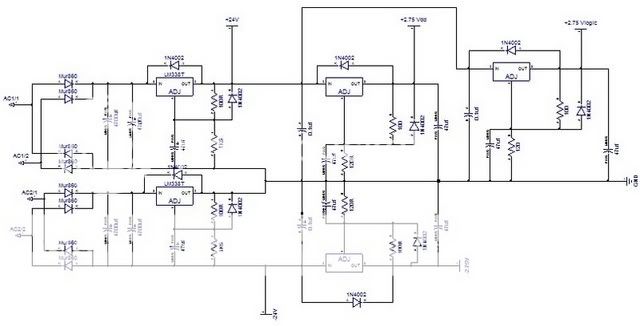
I would appreciate comments on this as I am about to start the PCB design on this one....
My Etchant, boards, developer, case and torroid arrive tomorrow. I want to get the parts ordered this week and start building on Friday (Day's holiday)
ANY help appreciated!!!
edit
A bigger version of the schematic
And I just noticed, i have 24v in for the outputs. It shoudl read 20V. I can only fit a 18-0 18-0 transformer in the case...
Thanks for the reply... I was begining to feel kinda lonely!
BWRX said:
The frequency response of the chip is perfectly fine for audio use. If you wish to add a low pass filter before the LM3875 choose a higher cutoff frequency. Move the cutoff frequency up to at least 40kHz to minimize its effect on the frequency and phase response in the audible frequency range.
The values I have gone for were pretty much on the advice at Peter Rogic's site, and orgionated from Joe Rassumen I believe.
I have opted for 1k/4.7nf/9K before the amps (lm3875) neg input.
This should give a drop off of -1.1db at 20Khz according to Pedja (I haven't worked out how the calculation is made) On Joes site he shows similar values in his ideal low pass figure. I dont have enough experiance to say wether this is to my tastes. (I gues that if the thing works I will be happy!)
BWRX said:
When choosing the gain you should consider the whole picture from source to speakers. Normally I prefer to set the gain so that the output is on the verge of clipping with a maximum source voltage. This prevents me (or anyone else) from ever horribly overdriving the amp. You mentioned that the source will be a sound card. The maximum output voltage for these can vary, so it's best to just measure it yourself. Generate a 1kHz full output test tone, turn up the volume the whole way, and measure it with a true RMS multimeter. That's the max RMS output voltage of the sound card. Generally this will be in the range of 1-2Vrms. Now you know the max input voltage to the LM3875 and can calculate the necessary gain based on the rail voltages you plan on using.
That is good advice. I will order up the parts for 26db gain. If its a little quite the GF wont mind. The 760i's she has (on loan from me) are pretty sensitive, and she does not play music too loud.
I also dont want to amplfy any noise from the max chip too much. I am making several boards anyway, so I can experiment with others.
BWRX said:
The resistor in series with the pot intput will work as you are thinking it will. You won't need to use the resistor unless the sound card has a very strong output, but it is a good idead to have provisions for it just in case.
Thanks for reassuring me. I was not sure wether to use a resitor or a divider, the maths told me a resistor would be ok. However with unknown values for the source, I am guessing. The datasheet says maximum peak of 2.75v This is 1.9rms. Wherever I read, this is a low figure for a source. My guess is that 20K is around the right value for this resitor, but maths is not my strong point! 40K will have the voltage. Anyone like to give me a clue here?
BWRX said:One thing I noticed is that you have the midbias pin connected to ground on your schematic. The dual supply schematic on page 6 of the MAX5440 datasheet shows that the midbias pin is not connected to anything.[/B]
The datasheet I downloaded has the bias attached to system ground (I hope that means signal ground.) The first schematic on the sheet shows it and the attched low outputs floating. This is setting the input voltage at 5.5v and 0v. I am balancing the chip in between voltages. At least I hope I am reading the sheet correctly?... The little triangle means ground in this application?
BWRX said:What resistors values do you need help selecting? There aren't that many you need to choose![/B]
First the input resistors. I guess another way of asking is what is a normal peak signal from a source (or the ranges that sources may reach)
Secondly the LED resistors. Now my understanding is that the LED resistors are switched to ground. This poses a problem. I want to use blue LED's. The forward voltage on these is higher than the 2.75v on the logic circuit. I chip shorts these to ground.
Will I be able to just feed them from a seperate (higher Votage supply?) Damn I wish I thought about this before!
Originally posted by BWRX
Also, don't forget that you will need a rotary encoder with a grey code output to work with the MAX5440.
I found one on flea bay. 20positions gray code continuous rotation with a push button. £1.99. The push button I can rig to either mute or balance.
I have finished the PCB I think.
Though it could do with a real going over with a toothcombe. I literally worked through Fri-Sat without sleep, And hit some more problems/mistakes today. There comes a point where I cant see the mistakes anymore.
I have also produced this Scematic for the PSU.
I would appreciate comments on this as I am about to start the PCB design on this one....
My Etchant, boards, developer, case and torroid arrive tomorrow. I want to get the parts ordered this week and start building on Friday (Day's holiday)
ANY help appreciated!!!
edit
A bigger version of the schematic
And I just noticed, i have 24v in for the outputs. It shoudl read 20V. I can only fit a 18-0 18-0 transformer in the case...
If you used 1k/4.7n/9k you would end up with a cutoff frequency of about 33kHz. I would suggest getting some 3.3n and 2.2n caps just to try. Since the 4.7n only introduces a small droop at 20kHz you probably won't even be able to tell the difference.
26dB (20V/V) is a good choice for the gain. Keep the input resistor value at 9k or higher. If you lower it's value you will increase the droop in the frequency response due to the low pass filter.
If the source is capable of 2Vrms output a 20k resistor in series with the pot will drop the source voltage to 2/3 (about 1.89Vpeak) when the pot is at the max of 40k. If the source is only capable of 1Vrms output then you won't need to use any series resistor.
Look at figure 6 on page 13 of the datasheet. That schematic is for a dual supply implementation. From what I can see, the midbias is not connected to anything. The midbias pin should only needed when using a single supply because you can't connect the low side of each pot to ground like you can when using a dual supply.
The datasheet is not very clear about what the LED are switched to. It appears as though they are switched to ground, unfortunately. What is the voltage drop across the blue LEDs at 10mA? If you apply a lower voltage across them they will still light up but will drop less voltage and not be as bright. A simple way around this is to use the LED open drain to ground outputs to control PNP transistors tied to the Vdd rail. When the LED output is open drain to ground it will pull the base of the PNP transistor to ground (through a resistor) and turn on the transistor. You can then wire the LEDs to the Vss rail and use the higher voltage drop LEDs. You can get 2N3906's for less than 10 cents a piece. Heck you may even have some laying around.
Your PSU schematic looks fine.
BWRX said:If you used 1k/4.7n/9k you would end up with a cutoff frequency of about 33kHz. I would suggest getting some 3.3n and 2.2n caps just to try. Since the 4.7n only introduces a small droop at 20kHz you probably won't even be able to tell the difference.
I will order up several values and try them.. Thanks
BWRX said:26dB (20V/V) is a good choice for the gain. Keep the input resistor value at 9k or higher. If you lower it's value you will increase the droop in the frequency response due to the low pass filter.
Will do..
BWRX said:If the source is capable of 2Vrms output a 20k resistor in series with the pot will drop the source voltage to 2/3 (about 1.89Vpeak) when the pot is at the max of 40k. If the source is only capable of 1Vrms output then you won't need to use any series resistor.
I will order a couple of values here. 5k seems more reasonable by the looks of things
BWRX said:Look at figure 6 on page 13 of the datasheet. That schematic is for a dual supply implementation. From what I can see, the midbias is not connected to anything. The midbias pin should only needed when using a single supply because you can't connect the low side of each pot to ground like you can when using a dual supply.
I was clearly looking at the sheet through very tired eyes.... Of course you are right. Thanks for pointing that out. I decided to take a break from the design side for a couple of days after that.. I think you can look at something for too long and become blind. Wood and trees come to mind
BWRX said:The datasheet is not very clear about what the LED are switched to. It appears as though they are switched to ground, unfortunately. What is the voltage drop across the blue LEDs at 10mA? If you apply a lower voltage across them they will still light up but will drop less voltage and not be as bright. A simple way around this is to use the LED open drain to ground outputs to control PNP transistors tied to the Vdd rail. When the LED output is open drain to ground it will pull the base of the PNP transistor to ground (through a resistor) and turn on the transistor. You can then wire the LEDs to the Vss rail and use the higher voltage drop LEDs. You can get 2N3906's for less than 10 cents a piece. Heck you may even have some laying around.
The Leds in my box right now are a bit unknown. However I looked up the datasheets for a few blues. Big problem there. Most will pass little to no current at 2.75v. The current they will pass I dont think will light them up. Red or yellow on the other hand pass current at much lower voltages, so will probably be fine. I guess that red might be OK. Blue is cooler... I will see if I have time to rework the circuit.
Another issue that crops up there is the LED indicator from the MAX works in increments. The lowest LED's will light up to full brightness, the final one dims bit by bit before going out. This allows for more increments to be represented. I think I could bias the transistors to give this effect, but I will have to look into it.
BWRX said:Your PSU schematic looks fine.
Thats a relief!
wxn said:SBLive 24bit doesn't fit there. I mean, pre EMU/XFI Creative products are simply not up to hi-fi standards, not to mention upper/hi end.
I'd recommend getting at least a prosumer grade sound card like EMU 1212, ESI Juli@. There are many choices.
Hi WXN. The soundblaster is not an ideal choice. It will do for now. The Mission speakers that this amp will be used with are not high end. A pair of Metronomes are next on the building list for the GF. After that I will look at a USB DAC. I am currently really enjoying the DDDAC1453MKII in my system. The sound from it is magical. I think I will probably go this route for the GF's system in the end. I may even adapt the design to produce a more compact version.
I have spent the last two nights producing a case for my DDDAC and its power supply. I am happy with the end result. Its based on the same HAmmond case that the amp design above is going to fit in. I really like the idea of producing a series of boards for this case. Amp, DAC, etc Watch this space...
Supplies are here
An update.
I forced myself to take a break from this project. The rising panic of a deadline was forcing errors.
However the other day I got my order from Rapid.
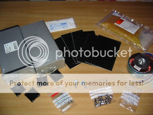
I also received a couple of Rotary Encoders from Flea bay as well as some other Bits and Bobs.
Here is the case that I will be using...

Looks pretty big till you put the torroid in...
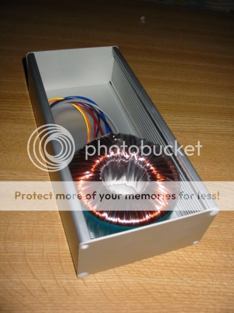
I really like the hammond 1455 case. It comes with black plastic surrounds to the end pieces. However it is well enough produced to do away with them..
I have spent the last couple of nights adapting the same case to house my DDDAC (Click to jump) . SO when I say a couple of nights off, i dont mean in front of the telly with a glass of red wine.
The GF comes back off a family holiday tomorrow. So no work will be done tomorrow. But I have a day off on Friday. Back to the computer for another serious CAD session...
An update.
I forced myself to take a break from this project. The rising panic of a deadline was forcing errors.
However the other day I got my order from Rapid.
I also received a couple of Rotary Encoders from Flea bay as well as some other Bits and Bobs.
Here is the case that I will be using...
Looks pretty big till you put the torroid in...
I really like the hammond 1455 case. It comes with black plastic surrounds to the end pieces. However it is well enough produced to do away with them..
I have spent the last couple of nights adapting the same case to house my DDDAC (Click to jump) . SO when I say a couple of nights off, i dont mean in front of the telly with a glass of red wine.
The GF comes back off a family holiday tomorrow. So no work will be done tomorrow
. But I have a day off on Friday. Back to the computer for another serious CAD session...Is it the MAX5440 will be at -12dB position upon every powerup? That seems too loud.
Anyway, I like the idea of graycode encoder control without MCU. If there's a way to access the resistor ladder directly without using the build-in opamp, I'll like to try it too.
Interersting project.
Please show us the LED display looks like
Anyway, I like the idea of graycode encoder control without MCU. If there's a way to access the resistor ladder directly without using the build-in opamp, I'll like to try it too.
Interersting project.
Please show us the LED display looks like
banana said:Is it the MAX5440 will be at -12dB position upon every powerup? That seems too loud.
Anyway, I like the idea of graycode encoder control without MCU. If there's a way to access the resistor ladder directly without using the build-in opamp, I'll like to try it too.
Interersting project.
Please show us the LED display looks like
Hi Banana
Yes the Datasheet states -12db on powerup, which does seem very loud. However I imagine that this will not be too much of a problem. There is a different feature of the chip called shutdown. When its pin is pulled low it goes into this mode. When returned from shutdown it remembers the previous pot position. Frankly I coudn't see how this differs from Mute. The power consumption of the chip is the same in either. So I haven't factored it in my design.
Unfortunately the resistor ladder can only be accessed via the op amp AFAIK. MAxim do other chips such as the DS1802 that dont include op amps, however the rotary encoder and LED feedback seems to only come on chips with op amps. I'm going to feed it a reasonable quality signal and hope the opamps are not too bad. The output looks fairly linear on the datasheet, but time will tell.
The LED display is simply 5 LED's. Its up to the user how this is implemented. Watch this space, I have a couple of ideas on this.
A bit more thought on the LED issue
I have had an idea on the LED front.
Using PNP transistors is a good idea. However it would mean redesigning my board.
Not a problem, there is plenty of space in that area that could house the required transistor circuit.. When I was thinking about the redesign though, I had a brainwave.
If I remove the led power rails, resitors and replace them with a small header, I can take this part of the ciruit off-board..
This allows me to fold in the caps at the top of the picture, basically it shortens my board by around 2cm.
The other advantage of doing this for me is it allows me to then produce more varients at the LED stage. For instance I can have a very low parts count circuit for red/yellow LED's, or a more complex board for using higher voltage drop LEDs. I can also attach the encoder to the design as it is board mount.
On a standard photo etc prototyping board say 100mm by 160mm I can fit both the AMP pcb and several variations of the LED/encoder mounting board. this will allow me experimentation for less money.
On the subject of transistors. I am a bit stumped as to how to imlement this. Here is where I am so far...
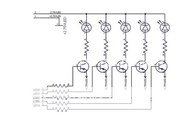
Now on the resitors after the collector, I am looking at values of around 100R. However i am baffled as to how to calculate the resitors that limit the current to the Base. I have read up on tutorials for doing this, But each one I have found assumes the supply voltage ground and the base to be one in the same. In my case the base will connect to 0v via its resitor (well 0.4 according to the maxim datasheet) Could someone help me out on the maths here?
Other than that I did not get any work done till now, My GF whisked me away to Perth to see Jools Holland play on friday, and we hit the Edinburgh Jazz festival today. I dont mind that kind of interuption at all. Tomorrow though I need to get this design finished ready for etching.
Any help as always apreciated..
Blair
I have had an idea on the LED front.
Using PNP transistors is a good idea. However it would mean redesigning my board.
Not a problem, there is plenty of space in that area that could house the required transistor circuit.. When I was thinking about the redesign though, I had a brainwave.
If I remove the led power rails, resitors and replace them with a small header, I can take this part of the ciruit off-board..
This allows me to fold in the caps at the top of the picture, basically it shortens my board by around 2cm.
The other advantage of doing this for me is it allows me to then produce more varients at the LED stage. For instance I can have a very low parts count circuit for red/yellow LED's, or a more complex board for using higher voltage drop LEDs. I can also attach the encoder to the design as it is board mount.
On a standard photo etc prototyping board say 100mm by 160mm I can fit both the AMP pcb and several variations of the LED/encoder mounting board. this will allow me experimentation for less money.
On the subject of transistors. I am a bit stumped as to how to imlement this. Here is where I am so far...
Now on the resitors after the collector, I am looking at values of around 100R. However i am baffled as to how to calculate the resitors that limit the current to the Base. I have read up on tutorials for doing this, But each one I have found assumes the supply voltage ground and the base to be one in the same. In my case the base will connect to 0v via its resitor (well 0.4 according to the maxim datasheet) Could someone help me out on the maths here?
Other than that I did not get any work done till now, My GF whisked me away to Perth to see Jools Holland play on friday, and we hit the Edinburgh Jazz festival today. I dont mind that kind of interuption at all. Tomorrow though I need to get this design finished ready for etching.
Any help as always apreciated..
Blair
Hi Blair. Your circuit schematic for the PNP switched LEDs looks good. Calculating the resistor values is really quite simple. You want the PNP transistors to act as switches so you want the base current to saturate the transistor. This will cause the Vce voltage to drop to around 0.2V. Using the Vce drop, the LED voltage drop, and the 5.5V across the rails, you can calculate the value of the LED current limiting resistor. Say you want around 10mA for each LED and the LEDs have a drop of 3V at 10mA. The value of the current limiting resistor should be about (5.5-0.2-3)/(0.01)=230ohms.
Since there will be about 10mA of collector current you just want the base current to be high enough to saturate the transistor. The minum DC current gain of a 2N3906 at Ic=10mA is around 100, so you want the base current, Ib, to be greater than about 10mA/100=0.1mA. Just to be sure the transistor is saturated you may want to shoot for Ib closer to 0.5mA. The open drain output of the chip will pull the base resistor to ground, so we can calculate the value of the base resistor to be about (2.75-0.7)/(0.0005)=4100ohms.
Kapeesh?
I think I get it, but let me feed it back in my own words...
The Vce drop is caused because the transistor when open is acting like a saturated diode, hence the 0.2v drop? The datasheet I am reading (On Semiconductor) gives
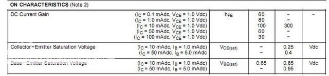
So lets make a guess then that at 20ma the voltage drop will be similar enough to 2.5Vdc
Now my blue LEDs have a voltage drop of 3.2 and 20-30ma so the calculation will be
(5.5-0.25-3.2)/(0.03) TO (5.5-0.25-3.2)/(0.02)=68R TO 102.5R
So 100R is correct for the resistor on the collector.
For the base, It is 20ma/100=0.2ma multiply by 5 and use
(2.75-0.7)/(0.002)=1025 or a 1K should be about right?
the 0.7 in the above calculation is the voltage drop from base to emiter?
Brian you are very patient by the way... Thanks for your help.
Does this mean that 5.5v is still not enough for the blue leds? Or can I run without the resistor
The Vce drop is caused because the transistor when open is acting like a saturated diode, hence the 0.2v drop? The datasheet I am reading (On Semiconductor) gives
So lets make a guess then that at 20ma the voltage drop will be similar enough to 2.5Vdc
Now my blue LEDs have a voltage drop of 3.2 and 20-30ma so the calculation will be
(5.5-0.25-3.2)/(0.03) TO (5.5-0.25-3.2)/(0.02)=68R TO 102.5R
So 100R is correct for the resistor on the collector.
For the base, It is 20ma/100=0.2ma multiply by 5 and use
(2.75-0.7)/(0.002)=1025 or a 1K should be about right?
the 0.7 in the above calculation is the voltage drop from base to emiter?
Brian you are very patient by the way... Thanks for your help.
Does this mean that 5.5v is still not enough for the blue leds? Or can I run without the resistor
banana said:Hi Blair,
How about using current mirror (current control current source), instead of common-emitter config to driver LEDs?
This should revive better the variable brightness, I guess
Hi Banana. i think that going with common emiter is better for me, as the part count is lower. And I dont want to go any further in the math than I have reached so far...

The variable brightness you mention?
Another issue that crops up there is the LED indicator from the MAX works in increments. The lowest LED's will light up to full brightness, the final one dims bit by bit before going out. This allows for more increments to be represented. I think I could bias the transistors to give this effect, but I will have to look into it.
I said htis earlier, though when I typed it I was tired. Looking at the datasheets more closely, this would appear to be true for the push button chip(MAX5486), but not the MAX5440. However the circuit will work with either the MAx 5440 or the 5486 if a trace is cut. The brightness is controlled by PWM.
I can make a sperate daughter board to control the LED's for the 5486. I dont know how the 35ns switching time will be affected by the transitors. I can give it a try, though the rotarty encoded version is my number 1 priority. I have samples of both chips however.
Been busy again today.
Made the changes to the main PCB, and a front panel designed incorporating the Rotary encoder and the LED's
The PCB I have managed to shorten considerably. This will allow me more space longitude wise in the case, It gives me more options in what is a tight space.
I did this by removing the LED supporting components off of the Main PCB. This also allows me more flexabilty in that I can add several differnent configs to one PCB and split it into the main PCB plus other front panels.
I will produce the first board with two options, one for a MAX 5440, the other for the MAX5486. So I can produce either a push button or rotary encoded design.
I also can factor in several options for LED placement with each board.
The first I have produced uses a 35mm aluminum knob on the encoder. The LED's are mounted behind the knob itself. So when lit up they will reflect light from underneath the knob. I should get a halo effect around the knob.
For the push button design, I expect to produce a straight forward line of LED's with push buttons at either end. Another option I may design uses a touch sensing chip instead of buttons.
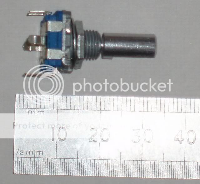
The encoder I got cheap off of E-bay. I unfortunately dont have details on its use, so the multimeter will be out.
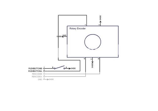
The encoder has 5 pins on it plus two ground lugs.
I am guessing that the pins denoted with A-C-B are the encoder inputs, the other two non labelled pins I am guessing will be the terminals for the push button selector.
I should find out tomorrow when I get a chance to test it with a meter. If not I will have to redesign the panel.
Anyone have any experiance with these?
Made the changes to the main PCB, and a front panel designed incorporating the Rotary encoder and the LED's
The PCB I have managed to shorten considerably. This will allow me more space longitude wise in the case, It gives me more options in what is a tight space.
I did this by removing the LED supporting components off of the Main PCB. This also allows me more flexabilty in that I can add several differnent configs to one PCB and split it into the main PCB plus other front panels.
I will produce the first board with two options, one for a MAX 5440, the other for the MAX5486. So I can produce either a push button or rotary encoded design.
I also can factor in several options for LED placement with each board.
The first I have produced uses a 35mm aluminum knob on the encoder. The LED's are mounted behind the knob itself. So when lit up they will reflect light from underneath the knob. I should get a halo effect around the knob.
For the push button design, I expect to produce a straight forward line of LED's with push buttons at either end. Another option I may design uses a touch sensing chip instead of buttons.
The encoder I got cheap off of E-bay. I unfortunately dont have details on its use, so the multimeter will be out.
The encoder has 5 pins on it plus two ground lugs.
I am guessing that the pins denoted with A-C-B are the encoder inputs, the other two non labelled pins I am guessing will be the terminals for the push button selector.
I should find out tomorrow when I get a chance to test it with a meter. If not I will have to redesign the panel.
Anyone have any experiance with these?
A PNP transistor is called as such because its internal structure is back to back PN junctions (a single PN junction is a diode). Without going into any real detail, the transistor will try to minimize the Vce voltage with increasing base current. If the emitter is connected to 5V and the collector is connected to the positive lead of an LED whose negative lead is connected to ground, the collector will sit at the same voltage that is across the LED regardless of the current going through the transistor. If a resistor is in series with the LED the transistor will try to minimize Vce if you pull enough currrent from the base to saturate the transistor.justblair said:The Vce drop is caused because the transistor when open is acting like a saturated diode, hence the 0.2v drop?
I bet those LEDs will be very bright at 20mA, so I would use at least 100ohms as you correctly calculated.justblair said:Now my blue LEDs have a voltage drop of 3.2 and 20-30ma so the calculation will be
(5.5-0.25-3.2)/(0.03) TO (5.5-0.25-3.2)/(0.02)=68R TO 102.5R
So 100R is correct for the resistor on the collector.
0.2mA*5 is 1mA or 0.001A not the 0.002 you used in the above caculation.justblair said:For the base, It is 20ma/100=0.2ma multiply by 5 and use
(2.75-0.7)/(0.002)=1025 or a 1K should be about right?
the 0.7 in the above calculation is the voltage drop from base to emiter?
Does this mean that 5.5v is still not enough for the blue leds? Or can I run without the resistor
You can short the current limiting resistor for maximum current if you find that the LEDs are too dim with the resistor in place. Most LEDs are very bright at 20mA though, unless you have special super bright high current, high intensity ones.
I never actually looked at the MAX5486 datasheet, but the MAX5440 definitely does not have variable brightness. Either the LED is on or it's off.justblair said:The variable brightness you mention?
I said htis earlier, though when I typed it I was tired. Looking at the datasheets more closely, this would appear to be true for the push button chip(MAX5486), but not the MAX5440.
BWRX said:
I bet those LEDs will be very bright at 20mA, so I would use at least 100ohms as you correctly calculated.
They are bright, however as they will be behind the volume knob, it is the reflected light that will be visible. i can experiment a bit with this to get just the correct levels.
BWRX said:
0.2mA*5 is 1mA or 0.001A not the 0.002 you used in the above caculation.
Doh...
BWRX said:
You can short the current limiting resistor for maximum current if you find that the LEDs are too dim with the resistor in place. Most LEDs are very bright at 20mA though, unless you have special super bright high current, high intensity ones.
I doubt that it will be necessay, but at least its an option. The effect i want will hopefully be subtle. Most listening will be done in the evenings.
BWRX said:
I never actually looked at the MAX5486 datasheet, but the MAX5440 definitely does not have variable brightness. Either the LED is on or it's off.
Yep I have to admit I blundered here origionally. I was working from both Datasheets. I want the design to offer either rotary or push button control. I assumed incorrectly that one chip was pretty similar to the other. I spotted my error today. La weekend i deinately overdid it.
However the design seems to be reaching the final stages. Just got to design the power supply PCB and have a general tidy up. That should be a lot simpler. I converted the schematic, and it pretty much came into a useable design when I ran the autoroute. Just have to compact it and get the placing right for the voltage outs. They will hopefully line up pretty closely with the boards inputs. That way I can minimise the cabling mess.
I didn't apreciate how much work would be involved in this design. However I am feeling pretty confident with it now. Lets hope I have not missed something major.

Power supply PCB laid out
Getting there with the final design. Got the power supply laid out...
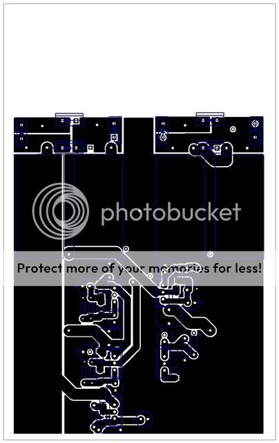

Going online tonight to place an order for parts. Give it a final once over and hopefully will be etching this week.
Please have a peruse and point out any blatant errors. I have designed the power supply pcb with all of the components mounted on the underside. The AC components are at the non signal end of my amp board, The Mur 760's will sit closer to the torroid as the power board is 120mm long as opposed to 85mm long. i have placed two of the Mur 860's at the very edge of the board. I will mount an alu plate to these which will serve as a ground shield to the amp board.
In mounting the boards "back to back" I will hopefully introduce as consistant a ground shield as I can between the power components and the amplifier components as possible.
It also means I can couple the heat producing components on the power to the base of the case, the heat producing components on the amp to the top. I have some heatsinks resued from some blown computer psu's which are the right design to do this for me.
Another advantage is that the wire connecting the boards together will line up producing the shortest run. Less messy cabling wise and good hopefully at avoiding adding junk to the DC voltages.
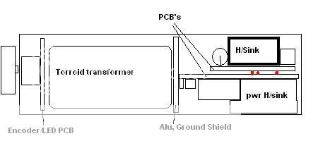
It's going to be tight, but hopefully not impossible. I can cut out unused bits of the pcb's if need be to allow rear connections etc
I have also lined up the regulators to allow me to use one continuous heat sink.
Getting there with the final design. Got the power supply laid out...
Going online tonight to place an order for parts. Give it a final once over and hopefully will be etching this week.
Please have a peruse and point out any blatant errors. I have designed the power supply pcb with all of the components mounted on the underside. The AC components are at the non signal end of my amp board, The Mur 760's will sit closer to the torroid as the power board is 120mm long as opposed to 85mm long. i have placed two of the Mur 860's at the very edge of the board. I will mount an alu plate to these which will serve as a ground shield to the amp board.
In mounting the boards "back to back" I will hopefully introduce as consistant a ground shield as I can between the power components and the amplifier components as possible.
It also means I can couple the heat producing components on the power to the base of the case, the heat producing components on the amp to the top. I have some heatsinks resued from some blown computer psu's which are the right design to do this for me.
Another advantage is that the wire connecting the boards together will line up producing the shortest run. Less messy cabling wise and good hopefully at avoiding adding junk to the DC voltages.
It's going to be tight, but hopefully not impossible. I can cut out unused bits of the pcb's if need be to allow rear connections etc
I have also lined up the regulators to allow me to use one continuous heat sink.
- Status
- This old topic is closed. If you want to reopen this topic, contact a moderator using the "Report Post" button.
- Home
- Amplifiers
- Chip Amps
- A rotary encoder controlled integrated chip amp LM3875