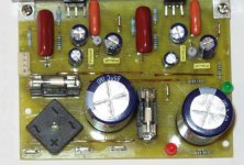
After seeing so much written about the TDA series of chip amps, I couldn't resist testing the TDA2050 which is so cheap over here.
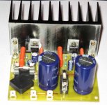
All parts are standard and the circuit is off the application note. Only the gain has been increased slightly due to component value changes. Input R = 47K and input C = 1uF ( Philips film )
Feed back is 47K and 1K with a 47uF electrolytic to ground.
Supply is +/- 25 volts dc from a 50 VA(!) torroid . I didn't have anything else.
The heat sink is too small for loud listening levels. The temperature was about 50 deg C I guess. I couldn't touch it for more than a second. Will check that tomorrow.
The sound was..... well...... incredible for a $1/- chip ! The first few minutes it seemed to be a bit rough in parts but as time went by it got better . Will have to let this play for a while before coming to conclusions. It looks like voice will be fine, deep bass is definitely there. The sound is tight and treble is clean .
However at times things are not OK as I seem to hear background trash. Mostly with complicated sounds. Might be some RF hash . Might need some compensation caps . Right now there are no compensation caps anywhere.
Supply cap is only 4700uF per rail but seems to be fine.
Never expected this to sound so good. Background noise is inaudible . Will check that again tomorrow. I'm going to get some more boards made and build a few more. Good to have some low cost good sounding rugged amps around for experimentation.
Cheers.
Attachments
The next day !
I did a listening test with a well known $ +1K amp. No names will be mentioned !
Surprise, surprise ! The TDA2050 beat it by a good margin in some areas !
The TDA was
1. Cleaner sounding but noisy vocals sound a bit rough.
( this could be a speaker problem (?)).
2. Bass was deeper and more distinct.
3. Midrange was slightly more forward ( certainly more clear cut ).
4. Generally, instruments had more air around each other.
5. Upper mids could sometimes be a bit brash.
6. Sound was more dynamic. The ref amp sounded compressed.
This was quite surprising . The ref amp sounded veiled in comparison ! Note that the listening levels were matched within 0.5db .
I think the LM3886 is better . Will also know how it compares with the TDA7293/94 in a short while.
For guys who are forced to stay on a very tight budget ( or do not want to spend more ) , the TDA2050 must be one of the best options available.
Some observations:
Running it at full blast .....just clipping ...at least 30 % of the time, it sounds good. Test signal was pop music off a CD player.
Heat sink temp rose to 60 deg C at the chips.
The 50VA torroid just got a bit warm.I was expecting it to get hot.
DC off set was less than 3mV on both channels.
A bigger torroid with 10,000uF caps might improve the sound some more. My speakers are nominally 8 ohms . They dip to about 5.8 ohms in the lower mids I think .
With some tweaks I think it will sound even better . As it is , it is great. I'm happy I tried it. Will have to refine the pcb a bit.
Great $1/- chip .
Tweaking it too much would be expensive and therefore pointless because the higher powered chips are also not very much more expensive and offer better performance.Over 90% of the cost goes towards the rest of the amp.
Cheers.
Day two !
This is the second day of testing and so far 125 page views but no comments !
As mentioned earlier , the transformer is currently a 50 VA torroid as that was all I had at hand. It’s too small but sounds surprisingly good and does not heat up much playing into 8 ohm speakers at full blast . I will be ordering a 100 or 120 VA 18-0-18 V unit .
The heat sink is also a bit small. I managed to reach 68 deg C playing loud on 88db/watt speakers. No harm done. In a proper case with fins on the outside it should be OK for music.
I changed the speakers and the occasional roughness in mid range mellowed down a lot. Then I changed the input cap to a Solen film cap. Now it really sounds very good. It might just sound as good as a LM3886 . I cannot vouch for that until I try it out in an A/B test.
What makes this amp so interesting is the heart of it cost next to nothing and it sounds so good with a respectable 20 watts per channel! But then that is true only for a DIY amp. This is also not for people who like to rock the house down.
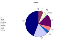
I made a pie chart to compare the cost of various parts of the amp. Looks interesing.
Resistors are less than 1% of the cost ! The ‘power devices’ are just 3% of the cost !
The casing ( Aluminum box ,RCA sockets and speaker binding posts, IEC socket, mains filter ) is the most expensive part.
Cheers.
This is the second day of testing and so far 125 page views but no comments !
As mentioned earlier , the transformer is currently a 50 VA torroid as that was all I had at hand. It’s too small but sounds surprisingly good and does not heat up much playing into 8 ohm speakers at full blast . I will be ordering a 100 or 120 VA 18-0-18 V unit .
The heat sink is also a bit small. I managed to reach 68 deg C playing loud on 88db/watt speakers. No harm done. In a proper case with fins on the outside it should be OK for music.
I changed the speakers and the occasional roughness in mid range mellowed down a lot. Then I changed the input cap to a Solen film cap. Now it really sounds very good. It might just sound as good as a LM3886 . I cannot vouch for that until I try it out in an A/B test.
What makes this amp so interesting is the heart of it cost next to nothing and it sounds so good with a respectable 20 watts per channel! But then that is true only for a DIY amp. This is also not for people who like to rock the house down.
I made a pie chart to compare the cost of various parts of the amp. Looks interesing.
Resistors are less than 1% of the cost ! The ‘power devices’ are just 3% of the cost !
The casing ( Aluminum box ,RCA sockets and speaker binding posts, IEC socket, mains filter ) is the most expensive part.
Cheers.
Attachments
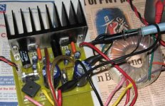
The board does carry a Zobel network as per the application note. 2.2 ohms ( vertically mounted ) and 0.47uF . Yes the board is reasonably star grounded .
I neglected the earth of the second channel and connected it the wrong way by a few mm and it had 100Hz supply ripple on the output ! I reconnected it to a different location and the 100Hz was gone. The board layout has to be done quite carefully.
The board will have to be modified slightly. This is a stereo board and with the existing supply it goes pretty loud.
I think the supply needs to be stiffer........bigger transformer and at least 10,000uF per rail.
I later added a 100pF capacitor at the input to filter out all RF trash . It didn't seem to matter audibly.
The amp sounds very good. I can't get over the fact that a $1 chip can sound so good.
Remember the 810 chip ....
On second thought...............
I watched the power supply rails when playing music. It dipped quite a bit on loud music. However the ripple levels did not go up too much though the average dc levels did drop more than it should.
So a bigger transformer might be more effective than increasing psu capacitance. So a 100 or 120 VA trafo with a minimum of 4,700uF per rail should do well. I'm targeting a 4 ohm load ( about 35 watts per channel ).
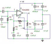
I've attached the circuit I've used with the component values shown on it.
The supply and supply fuse is shared between both channels.
I used 5 A slow blow because I had it . I've just changed it to 3A slow blow and it's working fine. I've used it about 4 hours now with the 3 A fuse and playing it pretty loud ( ocassional clipping).
This is a non inverting scheme and gain is +48 ( +33.6dB ).
So assuming a maximum theoretical 35 watts into 4 ohms , the input required would be just under 0.25 Volts.
Output is at pin 4 . The small +/- supply indicators near the opamp is part of the software package. You can ignore that.
Pin 5 is the +ve supply and pin 3 is the -ve supply.
Cheers.
Attachments
Hi,ashok said:I've attached the circuit I've used with the component values shown on it.
The supply and supply fuse is shared between both channels.
I used 5 A slow blow because I had it . I've just changed it to 3A slow blow and it's working fine. I've used it about 4 hours now with the 3 A fuse and playing it pretty loud ( ocassional clipping).
This is a non inverting scheme and gain is +48 ( +33.6dB ).
So assuming a maximum theoretical 35 watts into 4 ohms , the input required would be just under 0.25 Volts.
Output is at pin 4 . The small +/- supply indicators near the opamp is part of the software package. You can ignore that.
Pin 5 is the +ve supply and pin 3 is the -ve supply.
Cheers.
what gain? 1+[47/2k]=24.5 (+27.8db)
Why the decision to set NFB to F-3db=1.7Hz and then filter the input using C3 to F-3db= 7.2Hz?
Where is the T fuse?
If, in the supply, then maximum continuous peak current into your 4ohm load is about 4.2Apk (35W). I have found that a supply fuse (after the main smoothing) of about half this value will allow the amp to run reliably. You could therefore try F2.5A or even F2A and see which does not suffer nuisance blowing.
I just lost a long reply. So here is a gist of it.
1. Sorry I made a mistake. The first amp had again of 48. The next one was as shown in the diagram = 28 .
2. The capacitors are so because that's what I had. I had only that value Solen to use and it sounded better than others I had.
3. The fuse should have been between the 4700uF and the rest of the circuit.
4. I have only 3A nd 5 A slow blow fuses at hand at the moment!
Thanks for pointing out the errors.
As it's shown the amp sounds good.
Cheers.
A note on the Zobel network and stability.
I used the second design ( Gain 28dB ) for 2 days before realising that the zobel was missing . There were no instability problems . This might of course change with a difficult load.
I later added the zobel and there was of course no audible change in performance.
I used the second design ( Gain 28dB ) for 2 days before realising that the zobel was missing . There were no instability problems . This might of course change with a difficult load.
I later added the zobel and there was of course no audible change in performance.
Interesting tweaks.
I added some LED's to indicate the presence of power , both before and after fusing !
More interesting was my test with different input capacitors. I went round looking for a 1uF boxed MKP cap to fit my board but couldn't find any that were suitable. So I bought some brown unmarked 1uF film caps .These are most likely Chinese but could be Taiwanese too. Since it has absolutely no marking except the value it most likely is a Chinese brand.
Surprise surprise ! It sounds better than my Solen film cap !! Now that has stumped me. This film cap costs about 5 cents.
Basically it sounds cleaner between different sounds . So different instruments and voices have some air around them making them easier to follow. Overall it sounds easier on the ear on complex sounds but nothing seems to be sacrificed. No loss of low end or high end. It also appears to have more PRAT ! THAT is a very desireable quality.
Other similar cheap 1uF film caps , including Philips, do not sound the same. I tried them earlier.
This unit is much fatter than the Philips caps.
I plan to try these out in other circuits too to see if they work as well. Will surely help with my budget ! An opamp based headphone amp is in the offing . Will see what it does there.
Attachments
My boards are not a great design. Some chopped tracks and jumper wires above and below board. I hand painted the tracks.
I think you should stick to the board layout shown in the application note and you should be fine. I was planning on getting some boards made eventually but it hasn't reached that stage yet. Need to improve the layout or possibly redo the full layout again. I want to try out some experiments first.
Unfortunately I do not have enough free time to do all this quickly.
meepers , want a pcb ?
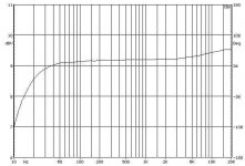
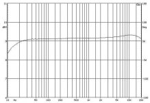
Today I did some measurements. The HF on this amp has a peak of about 1db or so at just beyond 20Khz ! I can only assume it's inherent to the chip. If I add a 39pf cap to the NFB resistor ( 47K ) it flattens it out and starts to roll off beyond 20Khz.
The peak is dependent on the speaker load . 4 ohm showing slightly less peaking. However the amp sounds fine and not 'bright ' because of this. I'll post some response plots later.
Distortion is poorer than an LM3886 but still quite low. I pulled out my LM3886 board to make some comparisons. The LM3886 is slightly better but not apparent on casual listening. The Lm3886 however has far more power ( with a dedicated 220 VA torroid ).
So that still means that the 2050 is an incredible bargain . The chip is one fifth the cost of a LM3886 chip . Today I measured the power output using a low quality 15-0-15 transformer . The output was only 12 watts into 8 ohms before the amp clipped due to a sagging power supply. However in listening tests the amp went pretty loud even with that.
Good tight bass too. Since my speakers are 8 ohm ( 88db/watt) rated they might be a comfortable load for the amp.
With less efficient speakers (86 db/watt ) the amp does lack a bit of steam if you want to play it loud. My 86db/watt speakers are also 4 ohms and so it adds to the power problem.
I'll post some measurements later.
Cheers.
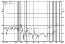
Distortion
Distortion at 1 watt with a 4 ohm load.
The picture gets clearer when you see the FFT . The 2050 has more harmonics visible than the LM3886 . That's probably why the LM3886 sounds cleaner . Not really too noticeable if you do not make a comparison side by side. By that I mean you listen to the amp without looking for differences.
Attachments
- Status
- This old topic is closed. If you want to reopen this topic, contact a moderator using the "Report Post" button.
- Home
- Amplifiers
- Chip Amps
- Another TDA2050 amp built and tested..............