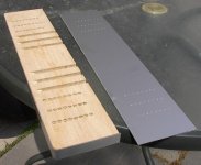
gbyleveldt said:Aha! I was wondering how much fun you would have putting all those leds and sliders on an alu frontplate, but I see you used wood. Neat idea!
Thanks. Actually would have preferred a solid aluminum face, but in the interest of saving money (and trying to find 3/4" ALU plate), I faked it.
Works just as good.
Attachments
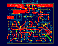
Here's the revised board layout, still based on the previously posted schematics.
I took Brian's advice, and made the layout more compact. Also optimized the filter stages and made them alike, and increased the ground area.
Still single sided with one jumper. I have the board size down to 2.5" x 2".
Anyway, like before I need an experienced eye or two to look it over for bug/problems. Also general comments are welcome.
Attachments
Hi John,
I've had a quick look at your layout and noticed that the ground connection to C14 gets squeezed quite tight by R17. C14 will draw large pulse currents which could raise the ground voltage in the tight area by a few millivolts. This is the usual cause of hum coming from a speaker. I suggest rotating C10 clockwise to allow the ground fill to connect under the cap.
A better connection could be achieved if the order of C10 and R17 was swapped on the schematic then rotate R17 clockwise. This would improve the ground further because the pin spacing of the resister is wider than the cap allowing more copper area.
The output track might also benefit from a little thickening-up.
Finally, shouldn't R24 have a inductor wired in parallel?
Nice one,
David.
Thanks David. That's what I'm looking for - an experienced eye to pick out the things I can't see.
I have made the changes you recommended - re-routing C10 and R17. Also I thinkened the output traces.
Although not shown, I will wind 10 turns of inductor wire around R24 attached to the leads (as recommended in Rod Elliot's design).
Any thoughts on power supply filtering? I have used large (8000 - 10000 uF) values for this chip before, but have seen others using as little as 1500uF on the rails - the idea being that large filter caps kill the midrange/treble. I have not tried this, so I don't have an opinion yet.
Perhaps, since the power supplies will be seperate - one for bass and one for mid/highs I could use different approaches for each - large caps on the bass for transients, small caps on the mid/high.
Best of both worlds?
Thoughts? Opinions?
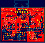
Reworked board layout:
I have made the changes you recommended - re-routing C10 and R17. Also I thinkened the output traces.
Although not shown, I will wind 10 turns of inductor wire around R24 attached to the leads (as recommended in Rod Elliot's design).
Any thoughts on power supply filtering? I have used large (8000 - 10000 uF) values for this chip before, but have seen others using as little as 1500uF on the rails - the idea being that large filter caps kill the midrange/treble. I have not tried this, so I don't have an opinion yet.
Perhaps, since the power supplies will be seperate - one for bass and one for mid/highs I could use different approaches for each - large caps on the bass for transients, small caps on the mid/high.
Best of both worlds?
Thoughts? Opinions?
Reworked board layout:
Attachments
That ground connection looks much better. I've learned to my cost what happens if grounding of reservoir caps is not done correctly!
One comment I forgot to mention last time was that it might be an idea to move C13 and C15 closer to the chip, or to tack a couple of extra decouplers on the rear of the PCB directly on the power pins. Also, one side of R14 needs to be connected and the -15v rail seems to be missing a decoupling cap.
As for power supply filtering, I'm an electronic engineer by trade so always follow solid engineering principles i.e. I dump as many caps as possible across the rails! I built an 8-channel gainclone last year with 48,000uF per rail on the main PSU board and 1000uF per rail per device locally. It sounds great to me...
if you are quoting Peter Daniel, I think he uses 96db/W speakers.MJL21193 said:but have seen others using as little as 1500uF on the rails - the idea being that large filter caps kill the midrange/treble.
daatkins said:
One comment I forgot to mention last time was that it might be an idea to move C13 and C15 closer to the chip, or to tack a couple of extra decouplers on the rear of the PCB directly on the power pins. Also, one side of R14 needs to be connected and the -15v rail seems to be missing a decoupling cap.
As for power supply filtering, I'm an electronic engineer by trade so always follow solid engineering principles i.e. I dump as many caps as possible across the rails! I built an 8-channel gainclone last year with 48,000uF per rail on the main PSU board and 1000uF per rail per device locally. It sounds great to me...
I will move C13, C15 closer (between the chip and C14, C16). Also will fix R14, which came undone with the last adjustments.
Decoupling on neither 15V rail (oops
). Will add these and one rail to rail.I'll use lots of capacitance then. The LM3886 amp I built before is for my speaker testing setup, it sounds fine too. A little hard to judge in mono, in my "lab". A Lm4780 paralell for a sub had 9600 uF, but that's bass only. Limited experience with these.
I have a multitude of 50volt 4700uF caps - I will paralell 3 per rail making 14100uF. Enough?
Also, as power supplies will be in thier own case, any considerations for the connecting wire? I have 18 gauge stranded that I was going to braid (3 conductor). Is this a good way , or run them side by side like ribbon cable?
AndrewT said:
if you are quoting Peter Daniel, I think he uses 96db/W speakers.
Yes, Peter and also I remember reading through a thread by carlosfm where he said the same thing.
I think the power supply should be smoothed as much as possible, but if it's not needed, or is detrimental to the sound quality, then why do it?
I logically can't understand why it would have an adverse effect on sound quality, but what do I know?
I'm going to go with conventional thinking on this and use lots of capacitance.
Andrew, what do you think of the board layout? As I have reduced the size, the cost of having these boards made has also fallen. About $2.50/board now.
MJL21193 said:what do you think of the board layout? As I have reduced the size, the cost of having these boards made has also fallen.
The suggestions David made were spot on, and your layout has improved accordingly. I've got a couple more suggestions for the layout. Move R21 so it is right next to the through holes for the chip pins. Then move R22 so it right below R21. Move R19 so it is parallel to C10. Shift C12 up and to the left a bit so it now about where R21 used to be. How much more would it cost to have a double sided board made from the place you're thinking about having these boards made? A better layout could be had if you went to a double sided board.
MJL21193 said:
Yes, Peter and also I remember reading through a thread by carlosfm where he said the same thing.
I think the power supply should be smoothed as much as possible, but if it's not needed, or is detrimental to the sound quality, then why do it?
I logically can't understand why it would have an adverse effect on sound quality, but what do I know?
I'm going to go with conventional thinking on this and use lots of capacitance.
Hi MJL21193,
I'm using both carlosfm's unreg snubberised PSU and LM3886. Really great sound from the monoblocks, each with a parallel LM3886 + 2 singles, so I've never tinkered with it. Besides I want the amps to be more versatile, rather than just being tweeter and mid amps. The single LM3886 drove the Scanspeak 8544/ss6600 mtm equally well passively or actively, but the parallel LM3886s drove the NHT/tonegen 1259s better than singles. That's carlosfm's unreg snubberised PSU ver 3, and LM3886 ver 4 btw in case you're interested.
Btw, like your work on your chassis. Very creative
BWRX said:
How much more would it cost to have a double sided board made from the place you're thinking about having these boards made? A better layout could be had if you went to a double sided board.
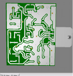
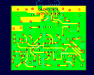
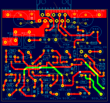
Ok, I bow to the pressure and have changed to a two sider.
This will be the final layout. Every time I make changes on the schematic level, it take 3-4 hours to re-layout, so hopefully, barring a few component moves here or there it's done.
I have added bypass caps for the 15 volt (C18, C19, C20) and have made the top side of the board the ground plane.
Here's the bottom:
Attachments
trats said:
That's carlosfm's unreg snubberised PSU ver 3, and LM3886 ver 4 btw in case you're interested.
Btw, like your work on your chassis. Very creative
I worked on the power supply last night. I have it conventional with 3 - 4700uF / rail plus .1 uF bypass caps. I will go with that for now, but the future holds much tinkering I'm sure
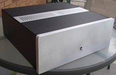
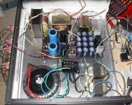
.Thanks, the chassis is the easy part for me. It's a gutted Akia amplifier that I bought on Ebay for $10. I made the back panel, the front and added the heatsinks.
The slide pots are in and the LED VU meters are almost done (48 LED's, six LM3915's).
I just need to finalize the active amp board layout to complete the unit.
Worked on power supply and power supply case all day (holiday here). For the most part the case is done, just needs a few odds and ends such as feet, a screw or two.
Need to get some fuses, a heavy power cord and start work on the soft start. For this, I'll be relying on Rod Elliot again (project 39). If anyone out there has a better circuit, let me know.
The power supply case:
Need to get some fuses, a heavy power cord and start work on the soft start. For this, I'll be relying on Rod Elliot again (project 39). If anyone out there has a better circuit, let me know.
The power supply case:
Attachments
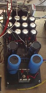
The power supplies used up almost every capacitor I had:
2 - 40 volt/6800 uF for the regulated +/-15v.
12 - 50 volt/4700 uF for the 2 +/-35v.
2 - 50 volt/8000 uF for the +/- 42v.
2 - 80 volt/10000 uF for the +/- 70v
Plus a bunch of 100nF bypass caps.
Wired point to point with 18 gauge wire, on a recycled circuit board that I painted black.
2 - 40 volt/6800 uF for the regulated +/-15v.
12 - 50 volt/4700 uF for the 2 +/-35v.
2 - 50 volt/8000 uF for the +/- 42v.
2 - 80 volt/10000 uF for the +/- 70v
Plus a bunch of 100nF bypass caps.
Wired point to point with 18 gauge wire, on a recycled circuit board that I painted black.
Attachments
MJL21193 said:Ok, I bow to the pressure and have changed to a two sider. This will be the final layout.
So that means I can't persuade you to change the components to surface mount?
Looking good John! I would move the large caps closer to the chip. Swap the position of C16 and POS_35 and do the same for C14 and NEG_35. You may also want to add some through hole connections to ground for your inputs and for speaker ground (unless you plan on connecting that to the supply ground off board). The last thing I would do is change the output trace so the resistor through holes are more in the center of the trace.
BWRX said:
So that means I can't persuade you to change the components to surface mount?
Looking good John! I would move the large caps closer to the chip. Swap the position of C16 and POS_35 and do the same for C14 and NEG_35. You may also want to add some through hole connections to ground for your inputs and for speaker ground (unless you plan on connecting that to the supply ground off board). The last thing I would do is change the output trace so the resistor through holes are more in the center of the trace.
Surface mount? Maybe next time
Will make the changes you suggest on the board layout, but not tonight - too tired.
Just spent 2 more hours working on the rats-nest that is the power supplies.
Nessasary evil - getting that done.

The place that I will order the boards from is:
http://www.futurlec.com/PCBService.shtml
Anyone with experience with them? Anyone that can suggest a better place?
My first time getting boards made (have done everything point to point up to now), so I'm a rookie.
The power supplies:
Attachments
How about making the resistors in the filter section as two resistors in series. This way one can choose more turn over frequencies than the standard resistor range will permit .
I am assuming that it is hard to get every single value in the 1 or 2% range. We certainly can't. Maybe you guys can !
Cheers.
I am assuming that it is hard to get every single value in the 1 or 2% range. We certainly can't. Maybe you guys can !
Cheers.
ashok said:How about making the resistors in the filter section as two resistors in series. This way one can choose more turn over frequencies than the standard resistor range will permit .
I am assuming that it is hard to get every single value
Hi ashok,
I have "piggybacked" resistors before in paralell to get the value I need. Should be enough room for that on the board.
I order all of the parts I need online, so no problem getting the correct values. With that said, the filter need not be exact, it can be very close to the frequncy and that would be fine.
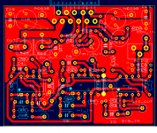
Finally, I have completed the layout, ready for production.
I will email the gerbers to Futurlec tonight.
Here are the final complete layouts.
Bottom copper:
Attachments
- Status
- This old topic is closed. If you want to reopen this topic, contact a moderator using the "Report Post" button.
- Home
- Amplifiers
- Chip Amps
- Active filter plus LM3886 - one board