MJL21193 said:
I will start by trying the completed channel again, to see if the crackling returns.
Well, good news. No evidence of crackling. It's been playing for a couple hours now at different volume levels.The active amps are working beautifully. I had forgotten how well they work.
Of course, this is just one channel. Hearing it with the other speaker with the passive filter really shows off the superiority of this method of amplification. Every detail is clearer and there's much better bass.
I am now re-invigorated and will focus my efforts to finishing this. One amp module to go and loose ends to tie up.
ashok said:
What software did you use to design the pcb ?Thanks,
Ashok.
Hi Ashok,
I used Ultiboard.
Thanks John.
Active speakers have always sounded better to my ears and the added benefit that they sound cleaner at higher levels. They also go louder than their individual amps can with normal passive crossovers.
My LM3886 test bed with LM3886T and Inverting configuration has a strange frequency response.
The otherwise flat response starts to droop very mildly from about 1Khz and then rises back to 0db at 20 Khz ( limit of what I can see ). At about 5Khz it is -0.06dB or so .
Miniscule of course but I don't see it in my other amps. Not even the TDA2050 amp . But that has a slightly rising response at 20 Khz !! Test system loop back response is perfectly flat and so is a Creek power amp.
I've never seen anyone report this .
Cheers.
Ashok
ashok said:Thanks John.
Active speakers have always sounded better to my ears and the added benefit that they sound cleaner at higher levels. They also go louder than their individual amps can with normal passive crossovers.
My LM3886 test bed with LM3886T and Inverting configuration has a strange frequency response.
The otherwise flat response starts to droop very mildly from about 1Khz and then rises back to 0db at 20 Khz ( limit of what I can see ). At about 5Khz it is -0.06dB or so .
Hi Ashok,
The difference between passive and active is like night and day, it's hard to deny the benefits. The passive filter smothers the sound and it doesn't do nearly as good a job of keeping the frequencies separate. With my passive crossover, I see much more cone movement on my midrange, movement I don't have on the active set-up.
What are you using to measure the amps? Still, that's not much of a drop (even though there should be none). Could it be parasitics in your test set-up?
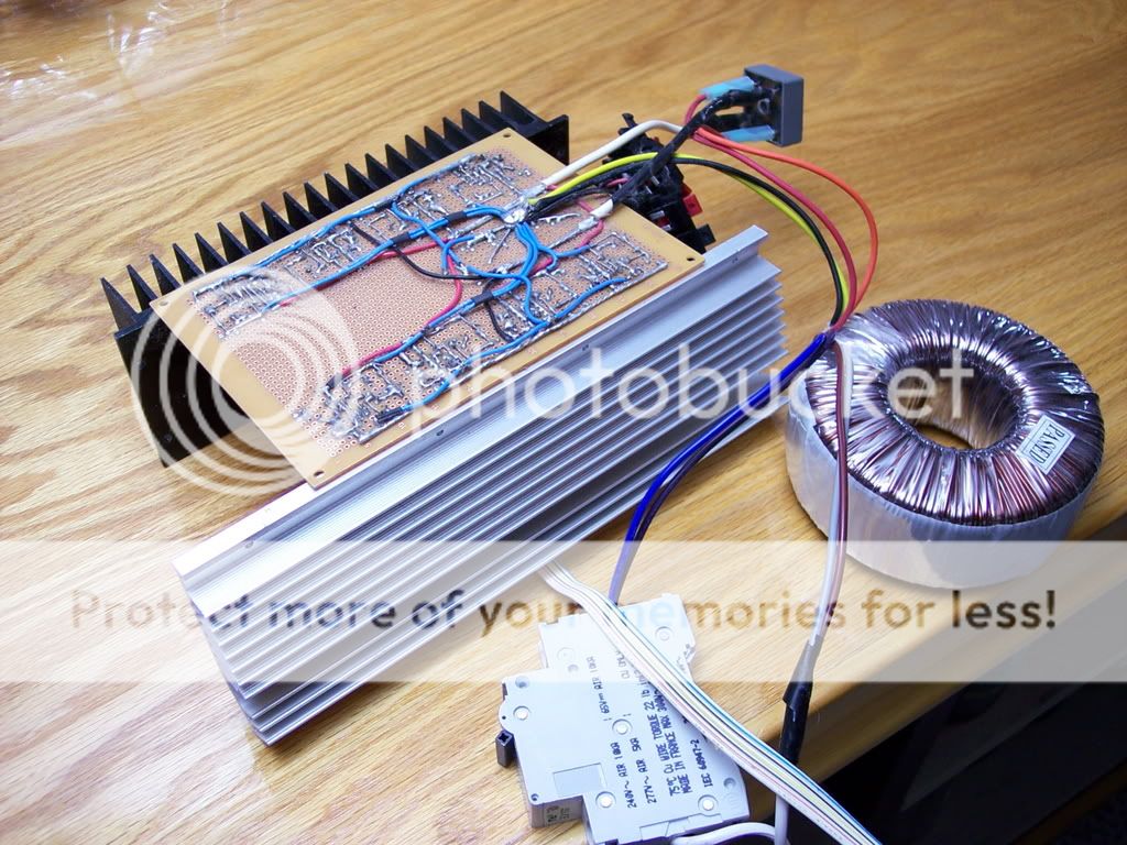
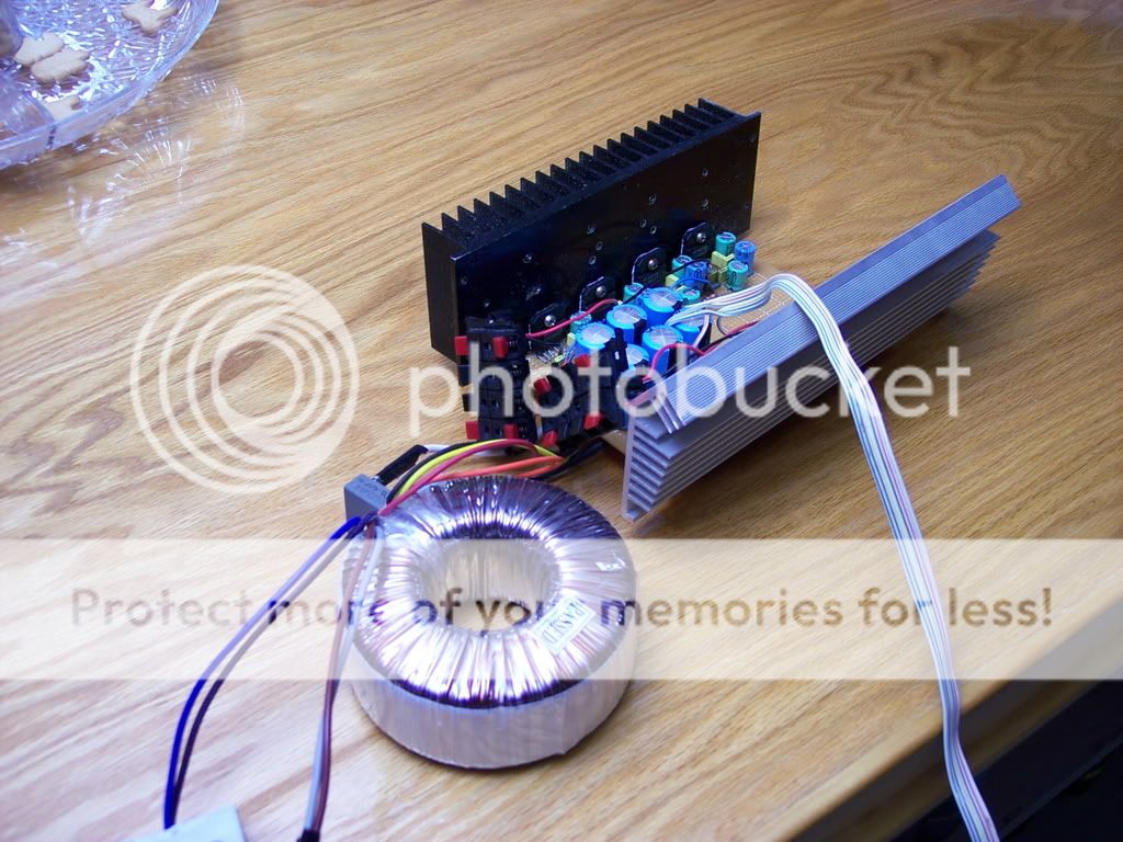
xplod1236 said:Sorry I didn't get a chance to reply earlier. I didn't have any boards made. Everything was done by hand, as can be seen in the pictures. The amp has been quiet since.
Hi Xplod,
Good looking job! I have done a few projects using perf board and p2p wiring. I've never had the kind of problems with that method as I'm having here, with a professionally made board.
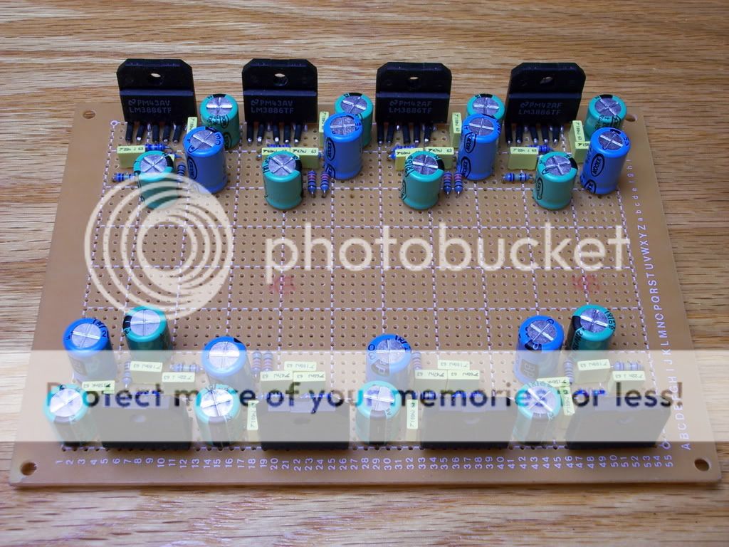
You say the crackling noise has stopped? I notice there are no op amps on your board. Does that mean you used the LM3886 as the filter? How does it work? Did you use a 2nd order filter or a 3rd? If I assume correctly, it's a 2 channel, 2 way active amp, right?
Lots of questions, I know. If you have a schematic of your design, I'd like to see it.
Yes, all the crackling has stopped. Actually, this is a 4-channel 2-way system. The filters are 2nd order using one opamp (the LM3886). It works well actually. It oscillates really bad when the signal cable is unplugged from my laptop, but with it connected, it's fine. (This was designed to work only with the laptop.) I played around with input resistors (signal to ground), but only a very low value resistor (47 ohm) stopped the oscillations. I never quite figured out why it oscillates. When it does, I get ~25 vac from each output. Low pass sections oscillate around 380 hz and the high pass sections around 9khz. The XO point is 3khz.
Recently (in the past two days), I put in buffer opamps so I could extend the signal cable (using a cat5 cable). The buffers are only temporary, since I'm planning on using pga2310s for volume control. With the buffers and no signal cable, I still get some noise, but it's not as bad as the oscillations I was getting before. Now I can plug in a 50+ ft ethernet cable, and it works just fine.")
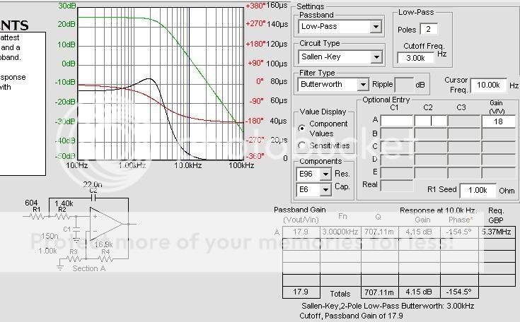
For the schematic, I used TI's filter pro. I don't remember the specifics, but I could look it up.
Recently (in the past two days), I put in buffer opamps so I could extend the signal cable (using a cat5 cable). The buffers are only temporary, since I'm planning on using pga2310s for volume control. With the buffers and no signal cable, I still get some noise, but it's not as bad as the oscillations I was getting before. Now I can plug in a 50+ ft ethernet cable, and it works just fine.
For the schematic, I used TI's filter pro. I don't remember the specifics, but I could look it up.
"...........Could it be parasitics ......."
Could be . I discovered that the second channel is fine. There is a slight difference in signal routing on both halves. Must be that.
In any case I'm changing the board design and that problem should go away.
I made my first three way active system in the early 80's ! Two 8 inch bass drivers , a 5 inch midrange and a 1 inch dome tweeter . Power amps were discrete 25watt units. All drivers were made by Philips . Used to sound great . Had to dismantle it long ago and the enclosures were still around till recently. I chopped one up to try out a new OB design ! Lot of good wood on it !
Is it inverting or non inverting?xplod1236 said:It oscillates really bad when the signal cable is unplugged from my laptop, but with it connected, it's fine. (This was designed to work only with the laptop.) I played around with input resistors (signal to ground), but only a very low value resistor (47 ohm) stopped the oscillations. I never quite figured out why it oscillates. When it does, I get ~25 vac from each output. .............................
Recently (in the past two days), I put in buffer opamps so I could extend the signal cable (using a cat5 cable). The buffers are only temporary, since I'm planning on using pga2310s for volume control. With the buffers and no signal cable, I still get some noise, but it's not as bad as the oscillations I was getting before. Now I can plug in a 50+ ft ethernet cable, and it works just fine.
For the schematic, I used TI's filter pro. I don't remember the specifics, but I could look it up.
Rs=47r seems excessively low to remove oscillation in a non-inverting arrangement. But Rs=infinity will lead to oscillation in an inverting arrangement.
xplod1236 said:
It oscillates really bad when the signal cable is unplugged from my laptop, but with it connected, it's fine. (This was designed to work only with the laptop.) I played around with input resistors (signal to ground), but only a very low value resistor (47 ohm) stopped the oscillations. I never quite figured out why it oscillates. When it does, I get ~25 vac from each output. Low pass sections oscillate around 380 hz and the high pass sections around 9khz. The XO point is 3khz.
For the schematic, I used TI's filter pro. I don't remember the specifics, but I could look it up.
Hi Xplod,
Do you have bypass caps on the rails at each chip?
If you are needing to nearly short the input to ground to stop the oscillation, maybe the filter configuration is a little off - could be positive feedback (you say the oscillation is frequency dependent). A schematic would help.
What's the gain on the chip amp? Low gain can result in oscillation.
ashok said:
I made my first three way active system in the early 80's !....
I chopped one up to try out a new OB design ! Lot of good wood on it !
Hi Ashok,
You were well ahead of your time on the active front!
Ditto for the recycling.
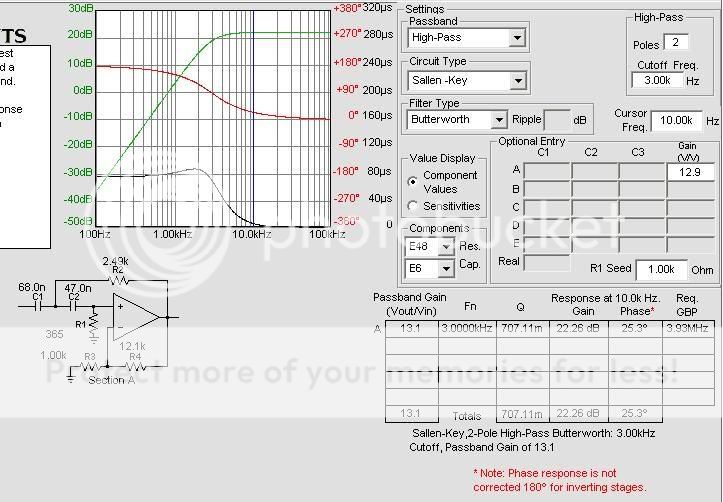
I have 220uf and .1uf on each rail next to each chip. The gains are 13 and 18 for HP/LP respectively, both of which meet the minimum gain requirement (10) for the chips. I have the inputs of both the HP and LP sections connected together; I'm not sure if that would make a difference. I also have a 3.3 uf cap between the inverting input resistor (1k) and ground, creating a high-pass filter around 70 hz, but I don't think that this would have any effect.
Hi,
inserting a DC blocking cap into the inverting input will create an output offset.
R1=r3//r4.
If you remove r3 from this equation then r1=r4 and r3 has to be reduced by a factor of 12 to bring the gain back to 22db.
But, why such a high gain? 0db or 4db are the usual Butterworth 2pole gain figures.
I particularly like the equal value component version of the S&K filter since all the components can be matched and it retains the ability to alter the Q independently of F.
Hi xplod1236,
When you disconnect it from the laptop, which (if any) grounds get disconnected (maybe inadvertently)?
With only the ground for the capacitor from the low-pass filter's non-inverting input to ground disconnected, it will oscillate at some low-ish frequency (probably between 1kHz and 10 kHz), basically from rail to rail or whatever the amp's output swings are.
If the ground for the LP's inverting input is also disconnected (from your 3.3uF cap, I presume), it will oscillate at a higher frequency (maybe on the order of 150 kHz), still basically rail to rail.
If only the two grounds for the LP and HP non-inverting inputs are disconnected (i.e. for the cap and the resistor), it will probably oscillate at a lower frequency than either of the two cases above, maybe below 200 Hz, but still rail to rail.
In all of the cases above, BOTH filters' outputs oscillated.
Oddly, if ONLY one of the inverting input grounds is disconnected (from one of your 3.3uF caps), the OTHER filter oscillates rail to rail (probably at an audio frequency), but the filter with the disconnected ground oscillates at a relatively low amplitude (but with a DC offset).
But, if all four of those signal grounds are disconnected, both outputs just tend to go to the negative rail, without much oscillation. (But I'm guessing that that behavior could be different, in a real-world circuit.) EDIT: If there is less than 100k Ohms from the input to ground, then oscillation appears at both filters' outputs, for this case.
There are other combinations of disconnected signal grounds that give other weird results.
I found all of this by simulating the two filter schematics you posted, with the inputs connected together, and 3.3uF caps inserted between the 1K inverting inputs' resistors and their grounds. I included a small ESR (about .03 Ohms) for each capacitor, but no other parasitics. For the opamps, I just used a model for the LT1028, since it was included in LT-Spice. However, I had no load connected to either filter's output.
To simulate disconnecting it from the laptop, I inserted a large resistance in series with the ideal 0.2-volt p-p 1kHz sine voltage source I was using for the input. Varying that large resistance did affect the results, somewhat, but mainly only the frequencies of oscillation, IIRC. I tried up to 10000 Megohms and still got basically the same results. (Without the source connected at all, of course, the ideal circuit's outputs would have always been flatlined. i.e. Something >0 is needed to trigger the oscillation, in a simulation such as this.) I did not use a large resistance for simulating the disconnection of the signal grounds. I just deleted their ground symbols, for that.
I don't know how well this simulation would resemble reality. And I don't know how your power supply and grounding are intended to be set up. But, if you weren't intending to disconnect any of those signal grounds, when the laptop was disconnected, maybe this will give you someplace to start looking for a problem. (Or, maybe some that you did intend to disconnect are staying connected.)
Good luck.
- Tom Gootee
http://www.fullnet.com/~tomg/index.html
xplod1236,
Forget my last post, mostly.
In that simulation, I think I must have had something connected between the input and ground, at least part of the time, without realizing it.
NOW, with a high-resistance source, it oscillates even with all four of the signal grounds connected to ground, unless there is a very small resistance connected from the input to ground, just as you reported. It actually even oscillates with the source completely disconnected. And both filters will oscillate even if their inputs are not connected to each other, or to any source. The lowpass output oscillates at about 67 Hz and the highpass at about 10 kHz, when simulated, both rail-to-rail.
BUT NOTE that connecting a small (0.15 uF) capacitor from the input to ground stops the oscillations, but, unfortunately, ALSO sends the lowpass filter's output to the negative rail (with and without the 3.3uF cap in place). (Note: In my simulation, 0.1uF from input to ground did not stop the oscillation. But 0.15 uF DID stop it.)
HOWEVER, adding a resistance, in parallel with a capacitor of at least 0.15uF, from the input to ground, stops the oscillation AND puts both outputs near zero volts.
A 100k resistor in parallel with a 0.15 uF cap from input to ground, with source disconnected, put the LP output at about -1.4 mV and the HP output at about 0.5 mV with no oscillation.
And using 50k to ground instead of 100k, paralleled by 0.15uF, put both outputs within 500 uV (microvolts) of zero volts.
So it looks like this: If you can tolerate >= approx 0.15uF of capacitance and <= 100k Ohms connected in parallel from the input to the ground, then it will not oscillate when the source is disconnected, and should keep the outputs reasonably-close to zero volts.
You might have to play-around with those R and C values, since this was just a simulation. Also, I should propbably note: With 100k/0.15uF from input to ground, I did not see any noticable difference in the circuit's response, with a source connected (compared to not having the RC from input to ground), for either the frequency response or the transient response for a squarewave.
Good luck.
- Tom Gootee
There is at least one possible problem with using an RC from input to ground to stop the oscillations:
The source's impedance will have to be very low, to avoid seeing a significant filter effect with the capacitor connected from input to ground.
Use the smallest-possible capacitance; only enough to kill the oscillation.
With 0.15 uF from input to gnd, for example: A 10-Ohm source impedance _might_ be OK. But 50 Ohms would probably not be OK at all.
- Status
- This old topic is closed. If you want to reopen this topic, contact a moderator using the "Report Post" button.
- Home
- Amplifiers
- Chip Amps
- Active filter plus LM3886 - one board