Hey everyone,
I have decided to build my fourth gainclone and would really like to fashion my own pcb. Nothing fancy, single sided etc. I would like to etch and drill it myself.
I have been looking around for some simple designs...LM3875 or 3886. Anyone have any suggestions or links. I am not looking to design the PCB myself (not yet atleast). I am just looking for some easy to work with designs.
Thanks for the help,
Wayne
There are a few floating around. Try searching for them. At the end of this thread sek posted a design for a single sided PCB that looked pretty good. Not sure if he or anyone else has made one yet.
However, I would suggest you have a go at designing it yourself. It's more fun that way")
However, I would suggest you have a go at designing it yourself. It's more fun that way
I am considering it....but seeing as I have never designed one before, I would like to have a few to help me prototype and build before jumping into my own.
I have searched the forums and Googled the subject a bit....but keep coming up with the same results...I am sure that their are more out there than what I am finding.
Thanks for the reposnse,
Wayne
I have searched the forums and Googled the subject a bit....but keep coming up with the same results...I am sure that their are more out there than what I am finding.
Thanks for the reposnse,
Wayne
I am at a similar stage.
My GF is getting the hifi bug and I was thinking about making a compact Gainclone for her.
Was thinking about combining a few ideas.... Jfet Buffer, lm3875(or 3876) digital volume control and a flat profile. My plan is to make an amp that will fit in a standard 100mm wide circuit board. Simple reason, I like the Hammond 1455 range of alu cases, and I reckon I can fit 4(at least) lm3875's in there to make a very compact biamp setup. The case measures 100mm*160mm*55mm and has slots to hold boards
I was thinking about making a series of modules that fit the hammond case so that I can experiment with various designs, ie making the buffer, volume control etc on seperate modules that are designed to be stacked.
What plans do you have?
So far I have built the decibel dungeon inverting design (point to point), But the pedjas jfet is very well reckoned. I am interested in what all the fuss is about, so this may be my next project.
what heat did the DD version give out?justblair said:My plan is to make an amp that will fit in a standard 100mm wide circuit board. Simple reason, I like the Hammond 1455 range of alu cases, and I reckon I can fit 4(at least) lm3875's in there to make a very compact biamp setup. The case measures 100mm*160mm*55mm and has slots to hold boards
......................So far I have built the decibel dungeon inverting design (point to point)..........
What size sink kept it cool?
How do you plan to make four chipamps and four sinks fit inside that case?
AndrewT said:
what heat did the DD version give out?
What size sink kept it cool?
How do you plan to make four chipamps and four sinks fit inside that case? [/QUOTE
Hi
The DD version doesn't seem too hot to me. I am using it with 12v supplied by four skynet smps 8080's. Heatsink wise they are bolted onto the top plate of the amp (420mm*55mm*3mm), in alu pods. This gets barely luke warm, even with the heat of the smps coming through it
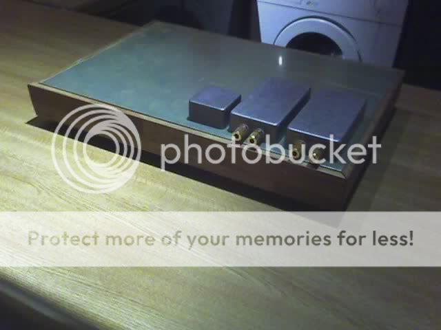
I took this piccy when I was laying out the four amp pods, it gives you an idea, in each pod, a lms387 is face down. Each of those alu boxes ends up about half full, though I removed the input caps which did take up a fair bit of space (mfp x2 4.7uf)
I had two ideas for the chips. One couple them thermally to the case via an alu or copper bar, I prefer this as it would leave the hammond case untouched. In this I would produce two stereo boards, with the chips mounted horizontally on the board rather than vertically.
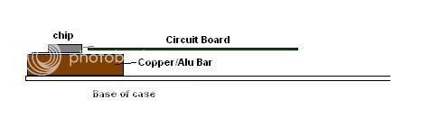
This diagram hopefully makes it clear
The second I came up with is to attach heatsinks to the top or back of the hammond case
There are loads more ways that it can be done of course.
I dont see a problem fitting four in there, well it will require a fair bit. The power supply would be in a seperate case.
WBoyd... Hope this isn't too far OT for you?
hi wboyd,
Here's a simple single-sided PCB for a LM3875 NIGC based on Peter Daniel's (BrianGT) schematic from a few years ago. The component values may have changed over the years.
You need to remove one pin on the LM3875 and the output may need a bigger hole. The physical size of the zobel components may be questionable, if you decide to use them.
WARNING: This is an untested PCB.
regards
Attachments
Nordic said:JB, very elegant implementation.
Thanks Nordic.
Do you mean the horizantally moutnted chip/heatsink combo?
AndrewT said:Hi Greg,
are the two extra holes up beside the C1 & C2 labels for film caps on the back of the PCB?
The r1 to r4 and input pins looks particularly neat and compact.
hi AndrewT,
Thanks. Then extra holes are for the option of using smaller sized caps and be as close as possible to the chip. I planned that all bypass caps to be soldered to the main caps leads under the PCB.
regards
Thanks so much to everyone and their great advice so far.
If I were to "copy" or build my own pcb, what is the preferred method....or what type of software application should I use. I would rather start simple.....and work my up from there. Starting with single sided, etc...
Here is my chip amp resume: BrianGT 3875 w/CarlosFM supply, and a total of 3 other's hand built in the P2P style. I thought that building my own PCB on a project such as this would give me a leg up on projects.
Once again thanks to everyone for their comments/suggestions. I have always found this forum to be one of the better ones that I have used.
Wayne
wboyd said:Thanks so much to everyone and their great advice so far.
If I were to "copy" or build my own pcb, what is the preferred method....or what type of software application should I use. I would rather start simple.....and work my up from there. Starting with single sided, etc...
My preferred method is to use the photo resist method for making my pcbs. You can use UV light for developing the board, however a very bright incandescant light will also do it in good time and with good accuracy. I personally use an old 650w everhead projector with the fresnel lense removed.
Advantages in using photo resist are that you can reuse your negs almost indefinately, and that it is easy to get very fine detail first time. Prepare for a disagreement here. Everyone has their favourites and some can become zealous in advocating theirs
As for applications I use Eagle, since its free, I have also used express pcb which is possibly easier to pick up and use (and free). I have also heard diptrace if very easy and cheap ($20)
Single sided should be ok, I am thinking about moving up to double sided. Just for the hell of it.
Here's my Gainclone PCB's for LM3886 chips:
http://www.darkmatter.myby.co.uk/LM3886/
They work fine on 25v rails, no problems
I made these using the "Toner Transfer" method - basically by doing a laser printout onto some good quality photo paper, and ironing that onto the PCB, then etching. It came out perfectly.
I used a 162x25x75mm heatsink for this, but to be honest it's probably overkill. I only ever got it warm when testing with some crappy old 4 ohm car speakers. The casing would probably work just fine, as would an old "slot 1" heatsink.
edit: this board is designed to be used with offboard power supply capacitance and rectifier. The two caps per channel on the board are only 330uF for local decoupling. I use a PCB that has 4x4700uF total (2 per rail) and the fuses too. There's a picture of that here
An externally hosted image should be here but it was not working when we last tested it.
http://www.darkmatter.myby.co.uk/LM3886/
They work fine on 25v rails, no problems
I made these using the "Toner Transfer" method - basically by doing a laser printout onto some good quality photo paper, and ironing that onto the PCB, then etching. It came out perfectly.
I used a 162x25x75mm heatsink for this, but to be honest it's probably overkill. I only ever got it warm when testing with some crappy old 4 ohm car speakers. The casing would probably work just fine, as would an old "slot 1" heatsink.
edit: this board is designed to be used with offboard power supply capacitance and rectifier. The two caps per channel on the board are only 330uF for local decoupling. I use a PCB that has 4x4700uF total (2 per rail) and the fuses too. There's a picture of that here
jaycee said:Here's my Gainclone PCB's for LM3886 chips:
An externally hosted image should be here but it was not working when we last tested it.
http://www.darkmatter.myby.co.uk/LM3886/
They work fine on 25v rails, no problems
I made these using the "Toner Transfer" method - basically by doing a laser printout onto some good quality photo paper, and ironing that onto the PCB, then etching. It came out perfectly.
I used a 162x25x75mm heatsink for this, but to be honest it's probably overkill. I only ever got it warm when testing with some crappy old 4 ohm car speakers. The casing would probably work just fine, as would an old "slot 1" heatsink.
edit: this board is designed to be used with offboard power supply capacitance and rectifier. The two caps per channel on the board are only 330uF for local decoupling. I use a PCB that has 4x4700uF total (2 per rail) and the fuses too. There's a picture of that here
I tried your links, not working for me
***Edit*** My router had a brain fart, can see them now
Ok....here is another quick question....is Eagle PCB hard to learn? I have downloaded it, but have not had the chance to take a look at it.
The method that I am intending on using is the heat transfer method...just basically creating an "iron-on" transfer.
Also, I noticed that schematics can be drawn in Eagle....will these transfer directly to a board...or is that created (drawn) separately?
Thanks again,
Wayne
The method that I am intending on using is the heat transfer method...just basically creating an "iron-on" transfer.
Also, I noticed that schematics can be drawn in Eagle....will these transfer directly to a board...or is that created (drawn) separately?
Thanks again,
Wayne
wboyd said:Ok....here is another quick question....is Eagle PCB hard to learn? I have downloaded it, but have not had the chance to take a look at it.
The method that I am intending on using is the heat transfer method...just basically creating an "iron-on" transfer.
Also, I noticed that schematics can be drawn in Eagle....will these transfer directly to a board...or is that created (drawn) separately?
Thanks again,
Wayne
I cant possibly explain this as well as some of the guides available...
It is not that hard to learn, though I think it takes a bit of practice to get good at using it. (I would not describe myself in that category).
The way that is works, is that you draw your schematics to begin with, and then when you switch to pcb view you are faced with an unpopulated pcb and beside it a set of components to drop on to the board. The components have all of the connections to each other from your schematic. As you place them around the connecttions sort of stretch (think of the components connected by elastic) then you simply (not really simple, this is where the practice and skill come in) lay traces using the pre exiting connections as your guide.
Simple? Well not really, but as I said a decent guide will take you through it step by step. Its actually harder to describe than it is to do it.
The only problem I repeatedly have is getting the components to link together on the schematic properly. I just can't seem to get the hang of it....
I noticed about 20 secs ago that diptrace is available in freeware (250pins limit, more than enough for me. Just downloading it just now for a play around with...
I learned EAGLE just by messing around with it. Sorry, that's not much help I guess....
Drawing schematics is quite easy - the hard part is laying out the board. It took me a few days to lay out the board for that Gainclone, and a good year to learn to use EAGLE effectively.
Once you get the hang of it though, you never want to go back to doing it the old way - pen and paper
wboyd: is the "iron on" transfer you refer to Press-n-Peel Blue ? I've heard that works quite well. For me, the toner transfer method works well enough - the key is to use good quality paper. Cheap photo paper is just plastic coated rubbish which melts. I use "Kodak Ultima" paper. It's fairly expensive but not as expensive as Press-n-Peel!
If you want to check again, there are now PDF copies of the solder side and silkscreen side of this board. Bear in mind that the silkscreen will need to be mirrored if you want to print it onto the board. I didn't bother with the silkscreen but it might be handy as a reference.
Jaycee,
I am referring to the toner transfer method. After looking at a few different methods....it seems to be the most cost effective (and easier) one around.
I have been looking at eagle for a couple of days and it does not seem to hard to learn...I am hoping that there is library with the a good set of national chips (I can't seem to get the pin spacing just right).
Anyway, I am hoping to have some type of prototype drawing done by tonight....or if anyone of you have some Eagle "templates" that you could send me via e-mail...please feel free. My address is wboyd (at) iglou (dot) com.
Thanks,
Wayne
There isn't a "device" (as EAGLE calls them) for the LM3886 as such.. I made my own.
The chip package itself IS in Eagle though, if you look in the "ref-packages" library you will find "TA11B" - that is the package the LM3886 uses.
You can copy this to your own library (I find it's best to make a library called "custom" and add your own parts to it), and then make a symbol and device for the LM3886. I could send you mine, but it's really important that you learn to create them.
Another free hint - for resistors and capacitors, use the "rcl" library. There's another library (i forget its name - i may have deleted it) that has some resistor layouts, but it's very inflexible compared to "rcl".
- Status
- This old topic is closed. If you want to reopen this topic, contact a moderator using the "Report Post" button.
- Home
- Amplifiers
- Chip Amps
- Gainclone PCB suggestions