Hi,
This is my first post on this forum, so hi to everyone out there") I used to be quite deep into overclocking processors, but recently I became hooked into making a Gainclone amp. I didn't have much experience (none, to be honest, at least not with audio stuff), so I decided to make it easy for myself, and ordered Peter Daniel's basic LM3875 kit. The amp isn't finished yet, but I already started thinking about possible ways of making it better. If anyone can make some suggestions as to what has the biggest impact on amp's sonics, I'll be very grateful.
I used to be quite deep into overclocking processors, but recently I became hooked into making a Gainclone amp. I didn't have much experience (none, to be honest, at least not with audio stuff), so I decided to make it easy for myself, and ordered Peter Daniel's basic LM3875 kit. The amp isn't finished yet, but I already started thinking about possible ways of making it better. If anyone can make some suggestions as to what has the biggest impact on amp's sonics, I'll be very grateful.
First, let me tell you where I am now:
- Nuvotem Talema trafo, 225VA, 2x18V (20.8V real), encapsulated.
- MUR680 diodes, ordinary resistors, Panasonic FC caps. No Zobel, snubber etc., just simple basic Peter's NI design.
- mains cable and plug from gutted computer PSU
- for internal power wiring - 2x0.75mm stranded copper cable in nice, thick&flexible insulation.
- for internal signal wiring - cable i made myself, cutting 3 leads off computer hard disk ATA ribbon, braiding them together and wrapping in insulating tape.
- a rather pathethic 10K pot, that I took off some old PC speakers
- heatsinks taken off broken PCs, they seem more than adequate for LM3875s.
- ordinary, nickel plated RCA sockets
- plastic 3A terminal block connectors as speaker binding posts.
As you can see, the config is a rather cheapskate/scavenger one. So, I started to think what could make an audible difference without terminally harming my wallet. I came up with a list of all possible points to upgrade:
- resistors (4 per amp board, 8 in total)
Upgrade to Caddock/Riken would cost 31-35$, and should bring significant improvement in noise level and overall clarity. I consider this a good option.
- small caps (4.7 or 10uF/50V, 2 on rectifier board)
Upgrade to Black Gate N would cost 7$. Probably not much to be gained here, but it's not expesive so I'd give it a try.
- big caps (1000 or 1500uF/50V, 2 on each amp board, 4 in total)
Upgrade to Black Gate STD would cost almost 70$ - ouch!... Quite possibly an audible improvement, but since Panasonic FC are really good, and the cost of upgrade is so high, I'd rather invest my money elsewhere, for now. (I don't event take into consideration an option of Black Gate 'N' series, they simply CAN'T be that good to be worth that kind of money)
- transformer
I've heard opinions that higher rail voltages tend to give better sound, but I was afraid I could run into problems if I changed speakers to some low impedance ones. I also read that 300VA isn't too much for a GC. So I might give some 2x25V 300VA trafo a try. But I'm going to do it later, as it would cost me around 90$... Yes, much later.
- power wire
Well, I can't honestly think what could I upgrade it to? It seems thick enough, and is easy to work with.
- signal wire
Since so little of it is needed, I was seriously considering upgrading to pure silver, teflon insulated wire (not that I honestly believe it would bring astonishing improvement, but it would be a nice thing to impress friends with. The thing is, I don't know which one to choose... Jupiter from PartsconneXion (silver solid core/cotton wrapped) looks nice and is inexpensive, but I don't know if it is thick enough - 28awg.
- signal sockets, speaker binding posts, mains cable&plugs
I'm not much of a 'cable believer', so if I upgrade connectors or mains wiring, it will be purely because of esthetic reasons. Or am I wrong?
Thanks in advance for any comments and suggestions.
This is my first post on this forum, so hi to everyone out there
I used to be quite deep into overclocking processors, but recently I became hooked into making a Gainclone amp. I didn't have much experience (none, to be honest, at least not with audio stuff), so I decided to make it easy for myself, and ordered Peter Daniel's basic LM3875 kit. The amp isn't finished yet, but I already started thinking about possible ways of making it better. If anyone can make some suggestions as to what has the biggest impact on amp's sonics, I'll be very grateful.First, let me tell you where I am now:
- Nuvotem Talema trafo, 225VA, 2x18V (20.8V real), encapsulated.
- MUR680 diodes, ordinary resistors, Panasonic FC caps. No Zobel, snubber etc., just simple basic Peter's NI design.
- mains cable and plug from gutted computer PSU
- for internal power wiring - 2x0.75mm stranded copper cable in nice, thick&flexible insulation.
- for internal signal wiring - cable i made myself, cutting 3 leads off computer hard disk ATA ribbon, braiding them together and wrapping in insulating tape.
- a rather pathethic 10K pot, that I took off some old PC speakers
- heatsinks taken off broken PCs, they seem more than adequate for LM3875s.
- ordinary, nickel plated RCA sockets
- plastic 3A terminal block connectors as speaker binding posts.
As you can see, the config is a rather cheapskate/scavenger one. So, I started to think what could make an audible difference without terminally harming my wallet. I came up with a list of all possible points to upgrade:
- resistors (4 per amp board, 8 in total)
Upgrade to Caddock/Riken would cost 31-35$, and should bring significant improvement in noise level and overall clarity. I consider this a good option.
- small caps (4.7 or 10uF/50V, 2 on rectifier board)
Upgrade to Black Gate N would cost 7$. Probably not much to be gained here, but it's not expesive so I'd give it a try.
- big caps (1000 or 1500uF/50V, 2 on each amp board, 4 in total)
Upgrade to Black Gate STD would cost almost 70$ - ouch!... Quite possibly an audible improvement, but since Panasonic FC are really good, and the cost of upgrade is so high, I'd rather invest my money elsewhere, for now. (I don't event take into consideration an option of Black Gate 'N' series, they simply CAN'T be that good to be worth that kind of money)
- transformer
I've heard opinions that higher rail voltages tend to give better sound, but I was afraid I could run into problems if I changed speakers to some low impedance ones. I also read that 300VA isn't too much for a GC. So I might give some 2x25V 300VA trafo a try. But I'm going to do it later, as it would cost me around 90$... Yes, much later.
- power wire
Well, I can't honestly think what could I upgrade it to? It seems thick enough, and is easy to work with.
- signal wire
Since so little of it is needed, I was seriously considering upgrading to pure silver, teflon insulated wire (not that I honestly believe it would bring astonishing improvement, but it would be a nice thing to impress friends with
. The thing is, I don't know which one to choose... Jupiter from PartsconneXion (silver solid core/cotton wrapped) looks nice and is inexpensive, but I don't know if it is thick enough - 28awg.- signal sockets, speaker binding posts, mains cable&plugs
I'm not much of a 'cable believer', so if I upgrade connectors or mains wiring, it will be purely because of esthetic reasons. Or am I wrong?
Thanks in advance for any comments and suggestions.
IMHO, and after trying most things, a simple GC is still the best GC!
Don't bother with BGs in a GC. Panasonic FCs and MUR 860's work well in a GC (although not necessarily elsewhere)
Solid core wiring for signal is fine (you don't need silver etc for those short lengths). Just keep it short and tidy.
Dual mono PSU is best with 37 volt rails (if you have 6-8 ohm speakers).
I prefer the PSU in a separate enclosure. I also prefer a non metallic enclosure for the amp.
Resistors - won't cost much so try what you fancy.
Zobel - won't cost much so try with and without.
:attn: One of the biggest improvments I got with GCing was to build a four channel amp and bi-amp the speakers.
Finally, remember that a lot depends on what goes before the GC! ie you may need an active pre or buffer stage.
Thanks for the response, Nuuk.
I forgot to mention 'preamp section' - I'm going to upgrade it to a simple Noble potentiometer - and probably leave it this way, until I'm stinkin' rich and can afford one of those fancy hi-end preamps
As to biamping - I was actually thinking about that, inspired by this crossover project. But for now, I think it's a bit too advanced for me Simple biamping is an interesting option though, especially that you say it brings significant improvement.
With signal wires - correct me if I'm wrong, but logically reasoning, a perfect signal cable should:
- have no capacitance (very important)
- have low resistance (quite important too)
- shield out any interference coming from higher voltaged wires/RF.
The first is achieved by insulating the core, with teflon being probably the best material to use.
The second is achieved by use of the best conductive material (i.e. silver); its thickness doesn't matter much as currents flowing in it are very low.
And the last can be done with braiding wires and/or shielding them.
With internal power wires, things change by 180 deg.:
- capacitance doesn't really matter much
- low resistance is prefferred, but not crucial
- fairly high current capability is important
- shielding is irrelevant as voltages are quite high
So, basically any copper cable of diameter, say, 0.75mm or more will do just fine.
This is how I thing wires work. Only thing I have no clue about is how does compare braided wire vs solid core one.
I know that braided are generally more flexible, they don't snap, and are easier to solder. But what is the trade-off? Is there any? I guess, there should be, and my bet was that they have higher capacitance than comparable solidcore. Can someone experienced shed some light on this, please?
I forgot to mention 'preamp section' - I'm going to upgrade it to a simple Noble potentiometer - and probably leave it this way, until I'm stinkin' rich and can afford one of those fancy hi-end preamps
As to biamping - I was actually thinking about that, inspired by this crossover project. But for now, I think it's a bit too advanced for me
Simple biamping is an interesting option though, especially that you say it brings significant improvement.With signal wires - correct me if I'm wrong, but logically reasoning, a perfect signal cable should:
- have no capacitance (very important)
- have low resistance (quite important too)
- shield out any interference coming from higher voltaged wires/RF.
The first is achieved by insulating the core, with teflon being probably the best material to use.
The second is achieved by use of the best conductive material (i.e. silver); its thickness doesn't matter much as currents flowing in it are very low.
And the last can be done with braiding wires and/or shielding them.
With internal power wires, things change by 180 deg.:
- capacitance doesn't really matter much
- low resistance is prefferred, but not crucial
- fairly high current capability is important
- shielding is irrelevant as voltages are quite high
So, basically any copper cable of diameter, say, 0.75mm or more will do just fine.
This is how I thing wires work. Only thing I have no clue about is how does compare braided wire vs solid core one.
I know that braided are generally more flexible, they don't snap, and are easier to solder. But what is the trade-off? Is there any? I guess, there should be, and my bet was that they have higher capacitance than comparable solidcore. Can someone experienced shed some light on this, please?
Hi,
without active pre-amp the high frequency could be rolled off.
"shielding is irrelevant as voltages are quite high"
actually, the high voltage signal can cause interference with the small signal on the pcb and adjacent wire, but shielding is not very effective at low frequency.
"I know that braided are generally more flexible, they don't snap, and are easier to solder. But what is the trade-off? Is there any? I guess, there should be, and my bet was that they have higher capacitance than comparable solidcore. Can someone experienced shed some light on this, please?"
This one is tougher to answer and subject to some controversy, so I'll try to explain minimally .
Capacitance is practically the same with solid core, it's governed by cable geometry and insulation material. cable that's not paired (figure 8, twisted pair) have lower capacitance but higher inductance.
Extreme example is : ribbon wire (Goertz) have higher capacitance and very low inductance.
the problem with cheap cable is, in some condition (humidity) the insulation material can attack the surface of the conductor, causing oxidation and corrosion. PVC / PVDC is known to be very bad in this regard. with stranded cable, the corrosion will be terrible, much worse than solid core. Solution : don't use PVC/PVDC
http://ecmweb.com/ops_maintenance/electric_case_suffocating_swine/
Hartono
without active pre-amp the high frequency could be rolled off.
"shielding is irrelevant as voltages are quite high"
actually, the high voltage signal can cause interference with the small signal on the pcb and adjacent wire, but shielding is not very effective at low frequency.
"I know that braided are generally more flexible, they don't snap, and are easier to solder. But what is the trade-off? Is there any? I guess, there should be, and my bet was that they have higher capacitance than comparable solidcore. Can someone experienced shed some light on this, please?"
This one is tougher to answer and subject to some controversy, so I'll try to explain minimally
.Capacitance is practically the same with solid core, it's governed by cable geometry and insulation material. cable that's not paired (figure 8, twisted pair) have lower capacitance but higher inductance.
Extreme example is : ribbon wire (Goertz) have higher capacitance and very low inductance.
the problem with cheap cable is, in some condition (humidity) the insulation material can attack the surface of the conductor, causing oxidation and corrosion. PVC / PVDC is known to be very bad in this regard. with stranded cable, the corrosion will be terrible, much worse than solid core. Solution : don't use PVC/PVDC
http://ecmweb.com/ops_maintenance/electric_case_suffocating_swine/
Hartono
Thanks for a good point, Hartono. I actually forgot about inductance completely (it was one of the things about electricity, that I had trouble understanding, to be honest).
I've just read a bit about it on Wikipedia, and it seems to me, that, basically, inductance derives from resistance (i.e. higher resistance -> higher inductance), length and diameter of the conductor. But why then, coaxial wires have so high inductance (which makes them useless for audio signals, from what I heard)? I initially thought they would make very nice signal wires - shielded and all...
Ahh... I wish I had paid more attention to physics back then, at school
As to "actually, the high voltage signal can cause interference with the small signal on the pcb and adjacent wire", you are of course absolutely right. I felt it, sort of intuitively, and kept power wires separated from signal ones, while designing casing for my GC.
Hi,
tin plated cable might be ok with PVC/PVDC since tin is acid resistant. but the pvc/pvdc still can release gases and might affect other metal inside the equipment. Tin plating is the cheap solution.
inductance is the inverse of capacitance , coaxial cable has high capacitance, and relatively low inductance, not the other way around. some coax inner conductor is made from copper clad steel , steel is not good for audio (magnetic) and add distortion.
Inductance in cable is usually more benign in audio frequency, unless a "single" conductor/cable is coiled (inductor,coil, the name is self explanatory). if one of the conductor carry + signal and the other - signal(or ground) the inductance is lowered (example: speaker cable).
I notice you used nickel plated connector , some nickel plating contain iron (magnetic).
Cheers,
Hartono
uncle_leon said:I've just read a bit about it on Wikipedia, and it seems to me, that, basically, inductance derives from resistance (
Nope, they're not tied together.
If you think of capacitance as being a resistance(impedance is a better word) to a change in voltage, you could think of inductance as a resistance(impedance) to change of current.
So, as a rule of thumb, capacitance is going to be more of a problem for low level (voltage based) signals, since a certain amount of the signal energy is going towards discharging and recharging the capacitance. Inductance doesn't really matter, since the current flow is so small.
For high level (current based) signals like speaker outputs, inductance will be more of a problem, since a lot of energy is taken trying to reverse the high current flow back and forth. Reasonable amounts of capacitance are easily swamped by the high current output.
There are, of course, exceptions. This is a very simplified description.
-Nick
Sorry for double posting, but why 'edit' feature on this forum is limited to 30mins after posting?...
Anyway, I was thinking about what Hartono said, regarding possible hi-freqency roll-off with passive preamp. And I think I found the perfect solution - a stepped attenuator. I found one, based on Vishay 1% resistors, for as little as 50AUD (yes, it is in Australian dollars and no, I have no clue as to how much would it cost to post it from there). I think this kind of solution will be quite hard to beat, even for good quality active preamps.
Anyway, I was thinking about what Hartono said, regarding possible hi-freqency roll-off with passive preamp. And I think I found the perfect solution - a stepped attenuator. I found one, based on Vishay 1% resistors, for as little as 50AUD (yes, it is in Australian dollars and no, I have no clue as to how much would it cost to post it from there). I think this kind of solution will be quite hard to beat, even for good quality active preamps.
Yes, I believe you are right regarding the capacitance on internal cables. In my chipamps, I've instead minimized the length to be insignificant. (input connector is right beside the amp chip), so I can't say how much difference it makes. I think not much.
As far as high frequency rolloff is concerned, it's not going to make a difference whether you use a pot or a stepped attenuator.
If you have a problem with high frequency rolloff, the only ways to fix it is to either increase the input impedance of the amp (making it more sensitive to noise) or reduce the loading on the input by buffering with an active preamp, which doesn't necessarily need to be complicated.
Whether this will be a problem or not depends on your source.
Try it and see.
That said, if you want very good channel balance, the stepped attenuator might be nice.
-Nick
Nuuk said:IMHO, and after trying most things, a simple GC is still the best GC!
Don't bother with BGs in a GC. Panasonic FCs and MUR 860's work well in a GC (although not necessarily elsewhere)
Solid core wiring for signal is fine (you don't need silver etc for those short lengths). Just keep it short and tidy.
Dual mono PSU is best with 37 volt rails (if you have 6-8 ohm speakers).
I prefer the PSU in a separate enclosure. I also prefer a non metallic enclosure for the amp.
Resistors - won't cost much so try what you fancy.
Zobel - won't cost much so try with and without.
:attn: One of the biggest improvments I got with GCing was to build a four channel amp and bi-amp the speakers.
Finally, remember that a lot depends on what goes before the GC! ie you may need an active pre or buffer stage.
That's right on, a simple GC is still the best GC and I was promoting it for last three years without basically changing anything in my initial circuit.
Regulated supplies, batteries, switching supplies, snubbers, Zobels, big caps, all came and are gone now (at least for me), and simple GC still rules.;-)
Panasonic FC caps are indeed the best value for the money and it's hard to improve on them.
The biggest change, in my system, came with using small BG N caps directly at the chip and larger BG STD at the rectifiers. That changed the sound in a right direction and for me there was no way back. Although some of my friends still prefer large BG STD at the amp.
The 10uF caps that come with a kit are not neccessary to be used, depending on a setup, the amp may actually sound better without them, so try both ways. I noticed that placing only one cap in negative supply may be better than using both of them (but that was mainly with BG N caps)
I would not go with standard resistors any longer though, as more"exotic" types offer more flavour and definition, but you need a right system to notice that. However, you may save by skipping input series resistor (220R in my kit) as that resistor is not really needed for the amp to function properly. Riken can be replaced by Kiwame, although there is slight difference in their signatures: Kiwame is more sweet and lacks the "bite" which I find quite desirable with Rikens (Rikens are out of production now, and if they are gone I will start using Kiwames). Input shunt 22k is equally important as 22k feedback resistor and Caddock MK132 is still best for me here.
Transformer is probably responsible for some 20% of good sound and if you use really cheap stuff the bass and PRAT may suffer. I find Plitrons quite good and only custom made toroids with amorphous cores were better, but I can't source them any longer.
PS wire makes probably 8% of the sound, for me Cardas is best suitable here, however much cheaper DH Labs hook up wire wasn't bad either and the difference was like comparing Rikens and Kiwames (too sweet for my taste).
Input signal wire is more critical than output wire, but I would not go with anything special here. Solid core silver from DH Labs is good, as well as gold plate copper I use most frequently now for signal. Just try to keep all connections short and you may be able to go away with most everything. For output, I use either Kimber or DH Labs (19ga). Altough one person I know about found GC addictive only after replacing signal wire with solid core silver. Cardas silver wire offered by Percy is pretty cheap and quite good.
Now, it may sound surprising to some, but chassis is actually pretty important and depending how you build it the sound may vary quite substantially. I can't offer any receipe here and I usually approach it with an open mind attitude, where everything can matter. My best creation so far was described here: http://www.diyaudio.com/forums/showthread.php?s=&threadid=76609&highlight=
Please note, that if you have balanced source, the bridged GC will be better than regular one, especially when it comes to dynamics and bottom end extention. But you need the speakers that are at least 6ohm.
The bi-amping is also a big advantage, and the GC will sound only as good as the rest of your system, if it sounds bad, the fault is usually somwhere else ;-)
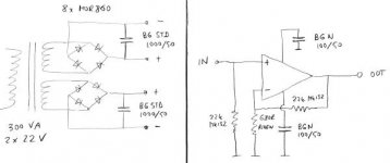
Attached is schemnatic of my Patek amp.
Attachments
BWRX said:
- Replace gainclone with class d amp*
*
Forget Class D amp. If you really want to upgrade from GC, use properly built Zv9 with tweeter crossover cap connected directly to the amp's output (bypassing the usual high value electrolytic).
Peter Daniel said:Forget Class D amp.
I would but I really like how some of them sound in my system
The higher efficiency is a nice benefit too.Hi uncle leon re: your question in Post #10 about the editing function. I think it is to stop people adjusting previous posts when they get into contenious debates. This current thread is very civilised but some are fairly intense debates and go on for months or years with a lot of "quoting" from the various participants. If the edit function had no time limit then the less scrupulous antagonists may be tempted to go back and "re write history" and "ammend the records" etc with all sorts of helpful/funny/scandalous results. Or simply they may just like to be able to change a previous faux pas so as to not look like a complete goose! I may be wrong but I think this is the reason. Seems reasonable to me.

- Status
- This old topic is closed. If you want to reopen this topic, contact a moderator using the "Report Post" button.
- Home
- Amplifiers
- Chip Amps
- The most effective Gainclone upgrades