An externally hosted image should be here but it was not working when we last tested it.
More important than the distortion of the test circuit is the distortion of the final amp. And current drive and slew rate will have a lot to do with that. Also you won't have as much XTALK with a properly designed LME49810 circuit(or crcuits, dual mono).
LM4702
XTALK Channel Separation (Note 11) f = 1kHz at Av = 30dB 85dB
SR Slew Rate VIN = 1.2VP-P, f = 10kHz square Wave, Outputs shorted 15 V/μs
LME49810
SR Slew Rate VIN = 1VP-P, f = 10kHz square Wave 50 V/μs(min)
Sure the distortion of the LM4702 looks great in the test configuration (no load, especially not a capacitive one). Driving a realistic power stage I would think the LME49810 would have a clear advantage, especially with MOSFETs.
So while thats an interesting graph, I would say its not very representative of the results you will get with a real power amplifier, even using National's excellent guidelines.
I would say the LME49810 is in part the result of lessons learned on the LM4702.
Cheers!
Russ
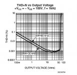
Also notice this graph from the LME49810 DS,
The standard (there is only one part) LM49810 easily surpasses the 4902C and equals (or betters under a real load) the 4902B.
When reading these data sheets always keep in mind, we are talking no load here. Add a load and the story will change dictated by the capability of the driver to adequately meet the demands of the load.
Attachments
the load on the source and sink is different on the two test boards --
with respect to slew rate -- (among other things) this is a function of the compensation capacitor value -- there is a forthcoming application note on compensating all of these driver chips. i have played around with this quite a bit and found that a couple tweaks were necessary to max the bandwidth without having the amplifier self destruct -- found that 30 pF was about right. i also found that the feedback network had to be compensated a bit -- i have run the amp thusly at 140 kHz without catastrophe!
in a new application note, National shows BD139 and BD140 transistors to drive a variety of MOSFETs (Renesas, Magnatec and Vishay) -- this is a good idea.
here's a comparison of the two driver chips -- they probably used 30kHz bw on their distortion analyzer.
An externally hosted image should be here but it was not working when we last tested it.
jackinnj said:with respect to slew rate -- (among other things) this is a function of the compensation capacitor value -- there is a forthcoming application note on compensating all of these driver chips.
Yes that will be a good app note, but I doubt it will change the maximum slew rate of the LM4702 which is stated in the data sheet. and I have read the FET app note, but you would not need any additional driver to use the LME49810 with many FETs.
jackinnj said:An externally hosted image should be here but it was not working when we last tested it.
You should note that that is the expensive LM4702B and not the more common LM4702C.
Russ White said:
You should note that that is the expensive LM4702B and not the more common LM4702C.
I was never able to get my Lateral MOSFET amplifier to attain the THD+N% levels of the reference design -- but it was (is) still very, very good -- the "B" has just become available in quantity and is a little more than twice the price of the "C".
I have an LM4702 amp sitting on the bench as we speak -- oscillating at 8.123 MHz.

Yes I bet the FET LM4702 amp sounds great. But even in the app note I think in most cases your are running the LM4702 very close to its margins with respect to the bias voltage. I guess what I am saying is I would doubt very much that with a real amp the LM4702 performs any better than a LME49810. You can look at the LME49810 as having a built in pre-driver for FETs etc.
Lets say you started with an LM4702 plus BD139 and BD140 transistors to drive FETs. Naturally your THD+N would be much worse than the LME49810 or LM4702 alone.
Also, I just don't see being able to compensate the LM4702 so it could match the LME49810's slew rate. Though I will anxiously await the app note to see what National says.
Russ White said:...According to the nice gentleman I spoke with there are more new devices on the way as well... Could it be a new dual part coming based on the 49810? Hmmmmm that would be sweet.")
Such as the new LME49860 - 44V Dual High Performance, High Fidelity Audio Operational Amplifier http://www.national.com/pf/LM/LME49860.html ?
The specs look the same as LME49720 http://www.national.com/pf/LM/LME49720.html (aka LM4562 http://www.national.com/pf/LM/LM4562.html) except the power supply limit has been raised +/- 5V.
jackinnj hinted at the 49860 back in March http://www.diyaudio.com/forums/showthread.php?s=&threadid=86276&perpage=50&pagenumber=5
ozonek said:Will NS continue their development on LM4702A (the top grade) while they now have a better design like LME49810? (dual version is coming soon?)
49810 is the evolution of the 4702 technology. A dual 49810 in a 4780-like package would make the 4702 obsolete. After all, they stuffed two 3886 dice in the 4780, so why not use the same trick again.
No question about it...this is an exciting new part It is very clear from the datasheets and application notes that the engineers at National used what they learned from the LM4702 to build an improved version.
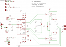
For those of you who are just as excited as me I have created library for this part, and put the datasheet schematic into Eagle. I will be coming up with a board design in the next few days (if the wife gives me enough free time that is ) I am intending on using BJT's and following the app note for now. I'll give MOSFETs a try later if it warrants it.
Have fun with the files (and yes I did misname the osense pin onsense).
G.
It is very clear from the datasheets and application notes that the engineers at National used what they learned from the LM4702 to build an improved version. For those of you who are just as excited as me I have created library for this part, and put the datasheet schematic into Eagle. I will be coming up with a board design in the next few days (if the wife gives me enough free time that is
) I am intending on using BJT's and following the app note for now. I'll give MOSFETs a try later if it warrants it. Have fun with the files (and yes I did misname the osense pin onsense).
G.
Attachments
Gcollier said:I will be coming up with a board design in the next few days (if the wife gives me enough free time that is
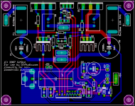
I hate to steal gcollier's thunder, but I was killing time and I came up with this board design (used my own symbol). It fits in the standard free Eagle 80x100mm footprint. What do y'all think? Be gentle on me, I'm pretty new at laying out boards. But I want to get better, so fire away.
I know there's one issue already, and that's the output sense line (the thin red line closest to KK2) runs parallel to the bias lines for quite some time, but I can't figure out how to fix that.
--Greg
Attachments
You hardly need the driver for this configuration. Since 50mA * 75 hFE(Min) = 3.75A, for MJL3281, good for 30V rails into 8 Ohms. This is about as hard as you'd want to push a single device anyway. But I laid it out as a demonstrator for doing larger output stages. If and when I get around to building any of this, I may try a driver-less single device output stage just for the heck of it.
I haven't shared any Eagle files before. Here's a .zip with the BRD and SCH files. Let me know if you need anything else.
--Greg
I haven't shared any Eagle files before. Here's a .zip with the BRD and SCH files. Let me know if you need anything else.
--Greg
Attachments
Thanks for the files they work perfectly fine for me
I hope to get around to experimenting with this soon. It will likely become the replacement in my guitar amp build which is currently using an LM4780. I'm going to be pushing 60 volts on each rail so I will have to make some adjustments, mostly to the output stage...but I really like your tidy layout.
Thanks Again!
G.
Hi Greg. According to your schematic you don't have AGND connected to PGND. You need to have them connected, preferably at one point.
Also, your 10uF input coupling caps with the 243ohm input resistors set the -3dB high pass frequency at 65Hz... That's pretty high and will be very audible. I would raise the values of the input and feedback resistors to get the -3dB frequency down around 10Hz or below so you don't have to increase the value of the coupling cap.
Also, your 10uF input coupling caps with the 243ohm input resistors set the -3dB high pass frequency at 65Hz... That's pretty high and will be very audible. I would raise the values of the input and feedback resistors to get the -3dB frequency down around 10Hz or below so you don't have to increase the value of the coupling cap.
BWRX said:Hi Greg. According to your schematic you don't have AGND connected to PGND. You need to have them connected, preferably at one point.
Also, your 10uF input coupling caps with the 243ohm input resistors set the -3dB high pass frequency at 65Hz... That's pretty high and will be very audible. I would raise the values of the input and feedback resistors to get the -3dB frequency down around 10Hz or below so you don't have to increase the value of the coupling cap.
The 10uf cap sees a resistance of around 7K to GND. A 10uf cap should be sufficient for that. But the Power GND and Signal GND does seem to be disconnected.
Cheers!
Russ
- Home
- Amplifiers
- Chip Amps
- LME49810 - a new cousin for LM4702