First off - I am very much a noob when it comes to electronics so please bear with my limited knowledge ")
I am in the finishing steps of assembling my chipamp and just for testing puropses I snagged a chassis from the electronics dump at work. After clearing out the old components then mains connection was left and I am curious as to why it looks like it does.
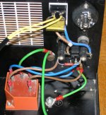
There is the big orange big box at the bottom where the mains power enters and comes out again (no resistance to speak of between the ins and outs. There is also the ground connection to the box... What is the purpose of this one?
The mains power hits the fuses, two of them and with a resistor between them? Why do one use this configuration? I thought it would suffice to put a single fuse here? The resistance is 1MOhm.
Then the capacitor connected at the switch, this one is rated 0.047µF 500V(AC). What is the benefit of this one?
All in all, are there any advantages or disadvantages with this connection with regard to audio? Should one just plug the mains directly to the trafo (with a fuse)?
/Jonas - as stated initially - noob but wishing to learn!
I am in the finishing steps of assembling my chipamp and just for testing puropses I snagged a chassis from the electronics dump at work. After clearing out the old components then mains connection was left and I am curious as to why it looks like it does.
There is the big orange big box at the bottom where the mains power enters and comes out again (no resistance to speak of between the ins and outs. There is also the ground connection to the box... What is the purpose of this one?
The mains power hits the fuses, two of them and with a resistor between them? Why do one use this configuration? I thought it would suffice to put a single fuse here? The resistance is 1MOhm.
Then the capacitor connected at the switch, this one is rated 0.047µF 500V(AC). What is the benefit of this one?
All in all, are there any advantages or disadvantages with this connection with regard to audio? Should one just plug the mains directly to the trafo (with a fuse)?
/Jonas - as stated initially - noob but wishing to learn!
Attachments
This is probably from a cabinet from an ex-piece of electronic communications gear? Had a small computer inside?
The big orange blocb is likely just an EMI filter. It would have inductors and such that attempt to clean up noise on the mains. It might be useful to know it's as much about keeping noise GENERATED by the enclosure from affecting nearby devices as it is about cleaning up dirty mains power for what's inside.
The capacitor is just a normal small transient grabber common on mains power designs.
My only guess about the fuse configuration is that one is a SLO-BLO and one is not.
Both of these would be just fine ahead of your mains transformer and should have no adverse effects on the chipamp if you decided to leave them in the mains power path.
Hi,
Do you use polarised mains sockets and plugs in Sweden?
If there is no likelyhood of swapping Live and Neutral then it's safer to remove the fuseholder in the Neutral line.
The possiblity of the Neutral fuse blowing and the Live fuse maintaining Live voltages inside the unit increases the risk of an accident if one were to open up an apparently dead amp when both lines are fused. In the UK this practice, of double fusing, is never used on domestic equipment.
I agree, the orange box is probably an interference suppressor.
hi,
No
Until Tintin's picture I have not seen dual fuse implementation in any gear here in Sweden, despite uncertain live - neutral polarity.
Do you use polarised mains sockets and plugs in Sweden?
No
Until Tintin's picture I have not seen dual fuse implementation in any gear here in Sweden, despite uncertain live - neutral polarity.
4fun & AndrewT:
Correct, I am not totally certain, but I think the device was built in the US.
pwillard:
No computer gear in the box itself, it used to be a power supply to some lab eqipment (a scintillator counter IIRC), the case was propped with a heavy transformer, a host of capacitors and some control electronics. I guess the EMI filter was there to not disturb the sensitive counting mechanism then. After inspecting the fuses, one of them is rated 2A and the other one 4A, no markings to hint of a slo-blo varitey though.
Thanks a lot for the valuable info! I'll keep these ones in the path for now then
If one only uses a single fuse (as is the normal practice, or?) on the mains would it make any difference security-wise? (I am good with bacteria and molecular biology, not electronics -yet)
But how can I tell which one is the neutral line? The plugs do not specify which one of the lines that are neutral? - One of the many things I yet do not grasp regarding AC power... What would be the potential danger if the netral and not the live wire have the fuse? I suppose this is 50% of all electronic eqipment connected?
What would be the point of having the resistor there in the first place?
What would be the point of having the resistor there in the first place?
and just as bad if only the neutral line is fused.The possiblity of the Neutral fuse blowing and the Live fuse maintaining Live voltages inside the unit increases the risk of an accident if one were to open up an apparently dead amp when both lines are fused
If your plugs are non polarised then it matters not which is live. Inverting the plug invites trouble.
The US used to run with non polarised plugs, but they eventually had the sense to change the rules (and they were on 110/120Vac).
The one with the Blue wire is the neutral.
Most places in the world do not have non-polarised plugs, therefore guaranteeing the Live wire is constant. The only time you see non-polarised plugs is the small figure-8 type connectors, and these are being phased out in favour of the C3 "Cloverleaf" connector which also include an Earth.
In an electrical installation, Neutral eventually connects to the same point as Earth/Ground. The danger of the Neutral fuse blowing is that it leaves the Live wire still powered. This can then form a circuit with any Earthed path and still cause a fire/electric shock.
The "Schuko" plug system should, IMO, have incorporated a polarising pin. There is a similar standard that DOES have a polarising pin. I've found this page very useful
(I think it's stupid we have all these different kinds of plugs - the world should just use the UK one - the safest one of all)
Most places in the world do not have non-polarised plugs, therefore guaranteeing the Live wire is constant. The only time you see non-polarised plugs is the small figure-8 type connectors, and these are being phased out in favour of the C3 "Cloverleaf" connector which also include an Earth.
In an electrical installation, Neutral eventually connects to the same point as Earth/Ground. The danger of the Neutral fuse blowing is that it leaves the Live wire still powered. This can then form a circuit with any Earthed path and still cause a fire/electric shock.
The "Schuko" plug system should, IMO, have incorporated a polarising pin. There is a similar standard that DOES have a polarising pin. I've found this page very useful
(I think it's stupid we have all these different kinds of plugs - the world should just use the UK one - the safest one of all
)- Status
- This old topic is closed. If you want to reopen this topic, contact a moderator using the "Report Post" button.
- Home
- Amplifiers
- Chip Amps
- Connecting the power - Why does it look this way?