i have this 225hcca(dig ref) i picked up a few months ago in a package deal, and i didnt check it before buying (hey the guy said they all worked)
soooo, the clipping lights stay on and the amp is putting out dc 21-22 volts.
before i check the numerous A56/06 drive transistors, is there anything that is usually suspect?
first i thought it was an opamp, so i changed them all since i had quite a few spares, no go...
in this package deal was a 'pioneer cd 1000 'crossover, which i suspect is what made the amp fail.
when i plug another hcca amp into the 'rear low' rca's of the crossover... it will also make the clipping lights stay on and causes the speaker to excurt and stay there (cant actually remember if it goes in or out)
any help greatly appreciated, btw i tried tracing one of the paths from an opamp and i 'think' it leads back to a white optocoupler, what does this optocoupler do for the opamp?
all diodes, output transistors, rectifying diodes are good.
havent checked the ps fets yet.
thanx, here we go again
The opto-couplers are used for turning on the PWM IC and for muting. The jfets that are connected to the opto-couplers are the muting transistors.
The op-amp in the center of the two channels is the one used in the feedback loop. Drive signal to both channels. Find the pin that has audio on it, that should be the good channel. Unplug the RCAs one at a time to confirm this. The other channel of the op-amp should have DC on its output pin. The DC should be of the opposite polarity of the DC on the outputs. If that's the case, there's an open/shorted/leakin driver component (transistor, resistor or diode).
Is the DC output voltage (on the speaker output) positive or negative?
Is the polarity of the voltage on the op-amp's output of the same or opposite polarity compared to the DC voltage on the speaker output?
the amp does this when there is no input and no rca's plugged in
since i didnt say earlier that this happens with no input signal..will wait for further instruction
"The op-amp in the center of the two channels is the one used in the feedback loop" :...... (the one between the resistor packs?between 2 small caps?)
amp is in pieces now, will have to reassemble first, before i can measure speaker output polarity.
ummmm, when i first got it, i thought the muting was defective so i cut out the 2n5639? muting transistors...do i need to put them back in before further diagnosis?
pins 5 and 6 = -0.638vdc...with rca's unplugged remains the same
pins 2 and 3 = -0.585vdc...with rca's unplugged remains the same
pins 4 and 8 = 13.31vdc
black lead on rca ground and red lead on pin 1 = 2.35/2.7vdc fluctuating...rca unplugged(1 or both) 2.35vdc remains constant
black lead on rca ground and red lead on pin 7 = 1.899vdc
this is for the opamp that is between the two resistor packs and between two caps (measuring the correct one?)
---------------------------------------------------------------------------------------------------
for the two opamps by the din plug im getting a constant 13.2vdc for pin 1 ...and 13.3vdc for pin 7
black lead to rca ground
---------------------------------------------------------------------------------------------------
speaker output polarity:
orange channel
orange wire/red lead
black orange wire/black lead
= + positive polarity............21.60vdc
-------------------------------------------
yellow channel
yellow wire/red lead
black yellow wire/black lead
= - negative polarity...........-21.60vdc
-------------------------------------------
bridged output
orange wire/red lead
black yellow wire/black lead
= + positive polarity...........0.006vdc
------------------------------------------
if i reverse the test leads all the polarities become the opposite.
if i put the black lead on pin 4 and the red lead on pin 8 at the same time i get 13.31vdc (shoudve been clearer, sorry)
with the black lead on rca ground and red lead on pin 4 i'm getting inconsistent readings...measured 3 times with 3 different values.... .041 .058 .035 (wtf) ...yes getting positive on pin 4
black lead on rca ground and red lead on pin 8, i get 13.98 vdc
if i reverse the leads the polarities are opposite
as far as the speaker outputs, i said 'speaker'...i didnt say both speakers although i shouldve...it was late lastnight and about to crash out ...but yes both channels are putting out dc.
am i measuring the right op-amp?
with the black lead on rca ground and red lead on pin 4 i'm getting inconsistent readings...measured 3 times with 3 different values.... .041 .058 .035 (wtf) ...yes getting positive on pin 4
black lead on rca ground and red lead on pin 8, i get 13.98 vdc
if i reverse the leads the polarities are opposite
as far as the speaker outputs, i said 'speaker'...i didnt say both speakers although i shouldve...it was late lastnight and about to crash out
...but yes both channels are putting out dc. am i measuring the right op-amp?
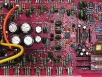
yes that is the board...
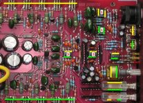
but this one has a square black plastic potentiometer that is mounted in the spare set of holes closer to the edge.
and instead of a big black diode by the black yellow striped and orange wires by the rectifying diodes...there are big grey resistors.
i removed the potentiometer to check if that was the problem, but nothing...
this is a really weird problem...its putting out the actual rail voltage.
am i measuring the right op-amp?
An externally hosted image should be here but it was not working when we last tested it.
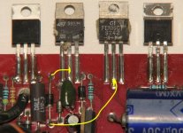
The one to the left is the one I needed you to measure but the voltages you measured indicate a problem with the negative regulator. The regulator problem has to be repaired first.
With the amp on, measure the DC voltage on the 3 legs of the 2n6491 left of your green arrow. The first leg should be approximately -16v, the second leg should be negative rail. The third leg should be approximately -15.3v.
With the amp on, measure the DC voltage on the 3 legs of the 2n6491 left of your green arrow. The first leg should be approximately -16v, the second leg should be negative rail. The third leg should be approximately -15.3v.
2n6491 from left to right (not upside down) by the arrow to the left bottom...with diodes attached to it.
leg 1= 0.031
leg 2= 0.662
leg 3= 0.664
i just checked those rectifiers the other day and they were good...will have to check again.
------------------------------------------
i just tried to remove the securing rails, with that technique you told me before...but this one is being extra sticky...and just broke the legs off of 3 ps fets in the top row in the pic dohhh!!! and the rail still isnt off...
will be back soon as soon as i can get the rails off for closer inspection.

ok replaced all the fets in the ps as well as the +/- rectifying diodes.
here are the measurements you asked for the 2n6491 one more time.
left pin.......... .037
center pin..... .669
right pin....... .670
didnt change much
whats that 2n6491 for? im getting confused between regulators and rectifiers.
here are the measurements you asked for the 2n6491 one more time.
left pin.......... .037
center pin..... .669
right pin....... .670
didnt change much
whats that 2n6491 for? im getting confused between regulators and rectifiers.
we have music !
but
the left channel doesnt have any gain control and hums, and the right channel is really scratchy when i turn the potentiometer.
some joker put in a 1.4 m ohm resistor where there should have been a 5.6 ohm, so i changed both for the 2N6491 and on the other side for the 2n6488.
----------------------------------------
orange channel
red lead on orange
black lead on black/orange stripe
-0.006vdc 0.011vac
---------------------------------------
yellow channel
red lead on yellow
black lead on yellow /black stripe
0.015vdc 0.011vac
--------------------------------------
bridged 0.015vac 0.008vdc
using a fluke 110 to measure and using a battery for power, so the hum isnt coming from a batt charger.
should i try changing the pot?
would you know what the reason was for orion to put different style pots in different mounting holes?
because if i have to change it, im going to have to use the regular type pot like in the picture...the pot they used in this amp is mounted in the next set of holes by the edge.
double thanx
because if i have to change it, im going to have to use the regular type pot like in the picture...the pot they used in this amp is mounted in the next set of holes by the edge.
double thanx
The difference was likely due to lead spacing and shaft/bushing length. The rear set of holes and the set of holes nearest the edge of the board are directly connected.
The black pots use the holes nearest the edge of the board. The smaller pots use the holes farthest away from the edge of the board.
If you have a scope, you can follow the signal through the op-amps. The gain pot goes to the very first op-amp (labeled '1'). If the signal is OK on the output of that op-amp, the pot is likely OK (or at least isn't the cause of the dead/humming channel).
Those RCA jacks are notoriously bad. Make sure the signal is getting to the center conductor of the RCA jack.
ok gotcha.
the left channel hums but still plays music...but it plays it at full tilt
when bridged mono its psychotic...very loud, just screams.
will check out the pot and switches, its late here now, and live in a condo, so dont want to wake the neighbors (this time)...time to crash out.
..forgot to ask...do you know what the value is for the round pot?
- Status
- This old topic is closed. If you want to reopen this topic, contact a moderator using the "Report Post" button.
- Home
- General Interest
- Car Audio
- 225 hcca putting out dc