Hi, I am repairing JL 300/4 amp that has missing output transistor. I was looking for exact replacement on the web but couldn’t find it.
I think that the missing transistor is exactly the same as #404 on the 2nd picture, but I am not 100% sure. I’d really appreciate it if you can help me out.
I think that the missing transistor is exactly the same as #404 on the 2nd picture, but I am not 100% sure. I’d really appreciate it if you can help me out.
An externally hosted image should be here but it was not working when we last tested it.
An externally hosted image should be here but it was not working when we last tested it.
Missing Mosfet
We have thousands of IRF540N in stock. These are IR parts.
Stephen Mantz
Zed Audio Corp
zedaudio@aol.com
We have thousands of IRF540N in stock. These are IR parts.
Stephen Mantz
Zed Audio Corp
zedaudio@aol.com
You have found excellent help.
Good evening Mr. Mantz")
I use : http://www.findchips.com/avail
But your in great hands With ZED Audio, thats for sure.
Good evening Mr. Mantz
I use : http://www.findchips.com/avail
But your in great hands With ZED Audio, thats for sure.
 I will replace both of them, but which ones are going to be the best replacement?
Fairchild IRF540A
http://www.futurecb.com/Boutique/ProductDetails.aspx?ProductIdentifier=IRF540AFAIRCHILD3021342
International Rectifier IRF540
http://www.futurecb.com/Boutique/Pr...dentifier=IRF540INTERNATIONALRECTIFIER3156700
NXP IRF540
http://www.futurecb.com/Boutique/ProductDetails.aspx?ProductIdentifier=IRF540NXP3490802
ST MICRO IRF540
http://www.futurecb.com/Boutique/ProductDetails.aspx?ProductIdentifier=IRF540STMICRO5984976
Does this stand for International Rectifier?
An externally hosted image should be here but it was not working when we last tested it.
That's an International Rectifier part.
Here's a good site if you need to find the company name from the logo. Surprisingly IR is not on the list.
http://info.electronicwerkstatt.de/bereiche/bauteile/ic_logo/
Both Fairchild and IR have been reliable for me.
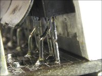
When you replace the transistor, you need to bend the center lead so that it can flex (see attached photo). If you solder it in place and the center lead is perfectly straight, the clamp may not exert enough force to hold the transistor against the sink. Clean the old grease and apply a thin layer of new grease. When the clamp is installed, make sure that the grease is displaced evenly around the transistor's perimeter. If it's not, it may not be mated properly and may overheat.
Here's a good site if you need to find the company name from the logo. Surprisingly IR is not on the list.
http://info.electronicwerkstatt.de/bereiche/bauteile/ic_logo/
Both Fairchild and IR have been reliable for me.
When you replace the transistor, you need to bend the center lead so that it can flex (see attached photo). If you solder it in place and the center lead is perfectly straight, the clamp may not exert enough force to hold the transistor against the sink. Clean the old grease and apply a thin layer of new grease. When the clamp is installed, make sure that the grease is displaced evenly around the transistor's perimeter. If it's not, it may not be mated properly and may overheat.
Attachments
Thanks Perry. While we are on this amp, does anyone know what is the purpose of the black asphalt coating on thyroid? Previous owner told me that this amp was once sent to an authorized JL repair shop where it was coated for some reason.
An externally hosted image should be here but it was not working when we last tested it.
Coatings are used for various reasons. Sometimes it's to secure the windings so the insulation doesn't wear through on the core or on other windings. Other times the coatings are used to quiet the windings. In some amps you can hear the audio being produced by the transformer's windings at high power levels. Sometimes, the noise is due to rapid changes in the duty cycle (the regulator operating to maintain the target voltage).
This is the first JL that I've seen with a heavily coated core.
This is the first JL that I've seen with a heavily coated core.
I received the replacement transistors, but I am not sure if they are the same with old ones...
An externally hosted image should be here but it was not working when we last tested it.
Thanks, I replaced both output transistors on the rear left channel but when I hooked up a speaker it plays very distorted and “Low Ohm” light came “On” and “Off” a few times. The rest of the channels play fine. 10A fuse does not blow and none of the parts inside seem to overheat.
The speaker terminals on the amp are not shorting?
and “Low Ohm” light came “On” and “Off” a few times. The rest of the channels play fine. 10A fuse does not blow and none of the parts inside seem to overheat. The speaker terminals on the amp are not shorting?
All leds are on the board are “on”. Thanks to your suggestion with bais current , I found that input terminals on the transistor pair are COMPLETELY open. Even if I set my ohmmeter to mega ohms, it doesn’t register anything. On the other, working transistor pairs this resistance is 9Mohm, 11Mohm, and 9Mohm.
So what can it be?
, I found that input terminals on the transistor pair are COMPLETELY open. Even if I set my ohmmeter to mega ohms, it doesn’t register anything. On the other, working transistor pairs this resistance is 9Mohm, 11Mohm, and 9Mohm. So what can it be?
Open gate resistors?
Open source resistors?
Open driver transistors on the driver board?
Follow the traces back from the gates of the outputs to the driver boards and compare the channels where the gates of the outputs connect to the driver boards. Are the resistance readings different there?
Open source resistors?
Open driver transistors on the driver board?
Follow the traces back from the gates of the outputs to the driver boards and compare the channels where the gates of the outputs connect to the driver boards. Are the resistance readings different there?


A couple of notes (please don't be offended).
The solder pads were pulled/damaged because too much stress was applied to the board. This is generally due to not using enough heat or taking too long to remove the transistor.
If you have a good iron, apply a lot of new solder to the connections of the transistor you're trying to remove. Lay your iron across all 3 solder connections. The transistor should come out of the board within 3-4 seconds with little or no stress. If the transistors won't come out easily even though the solder is completely molten through the board, it could be due to burrs on the leads. Cut them with flush cutters before adding the new solder. This should remove the burr and allow it to be easily removed.
If you're iron is not getting hot enough, cut the legs from the transistor as close to the body of the transistor as possible. Apply new solder to the connection and pull the leg of the transistor out with a pair of hemostats or pliers. You want the leads as long as possible because it will prevent the pliers/hemostats ffrom sinking too much heat through the lead (as it would do if you were holding it nearer to the solder connection).
If your iron doesn't get hot enough, you may need to heat the connection from the side of the board that has the largest copper area.
The solder you're using may be the wrong type or too old. The solder connection should be shiny and smooth. I generally recommend Kester 44 but there are other good choices also.
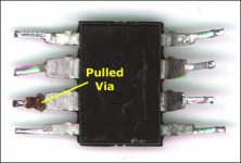
The right-most transistor looks like the via (copper plated feedthrough) may have been pulled (see attached). You may want to solder it from the top.
When you remove transistors that don't readily pull out of the board, you need to look at the leads to see if you see anything like the pulled via in the photo. If you see that the via is damaged, you need to make sure that you take that into account when replacing the components.
The solder pads were pulled/damaged because too much stress was applied to the board. This is generally due to not using enough heat or taking too long to remove the transistor.
If you have a good iron, apply a lot of new solder to the connections of the transistor you're trying to remove. Lay your iron across all 3 solder connections. The transistor should come out of the board within 3-4 seconds with little or no stress. If the transistors won't come out easily even though the solder is completely molten through the board, it could be due to burrs on the leads. Cut them with flush cutters before adding the new solder. This should remove the burr and allow it to be easily removed.
If you're iron is not getting hot enough, cut the legs from the transistor as close to the body of the transistor as possible. Apply new solder to the connection and pull the leg of the transistor out with a pair of hemostats or pliers. You want the leads as long as possible because it will prevent the pliers/hemostats ffrom sinking too much heat through the lead (as it would do if you were holding it nearer to the solder connection).
If your iron doesn't get hot enough, you may need to heat the connection from the side of the board that has the largest copper area.
The solder you're using may be the wrong type or too old. The solder connection should be shiny and smooth. I generally recommend Kester 44 but there are other good choices also.
The right-most transistor looks like the via (copper plated feedthrough) may have been pulled (see attached). You may want to solder it from the top.
When you remove transistors that don't readily pull out of the board, you need to look at the leads to see if you see anything like the pulled via in the photo. If you see that the via is damaged, you need to make sure that you take that into account when replacing the components.
Attachments
Perry Babin said:A couple of notes (please don't be offended).
Perry, are you kidding me? Why I would be offended - you are like a teacher to me...

I think my iron gets hot enough at 30W. I just did not know all those tricks and I pulled transistors with pliers leg by leg...
My solider looks this way because I am not heating it up too much. I am afraid that heat can travel into the transistor and melt something inside.
Thanks for the great info!

It's virtually impossible to damage a transistor soldering the leads with anything resembling a normal soldering iron. Of course, it's always good to be cautious.
I used to be concerned until I began soldering Rockfords transistors onto the insulators. The body of the transistor probably gets 200-300° hotter than you could ever get it soldering the leads.
If your iron's getting hot enough, it should take less than 2 seconds to make a good solder connection (on most devices). On something with a lot of mass that's soldered to a large ground plane of heavy copper, it may take up to ~5 seconds to get it hot enough but that's relatively unusual. Generally, the only time you see that is when you're replacing large snap-mount capacitors.
- Status
- This old topic is closed. If you want to reopen this topic, contact a moderator using the "Report Post" button.
- Home
- General Interest
- Car Audio
- Please help me find missing transistor...