I have an old shcool orion 2150 gx. awesome amp from what I hear. I know orion used to make some great stuff.I'd love to get this thing working again.When it was given to me originally I believe it would turn on but had no output.As far as I can remember I don't think it even will power on anymore.I am a total noob to this game.I have a basic understanding of electronics but I am totally lost when it comes to troubleshooting this type of stuff.I wanna get this amp rolling but I have no idea where to start.Can anyone possibly lend a helping hand?
If it has a TL494 (or tl594) in the supply, you need to connect it to a power source (including remote) via a 5-10 amp fuse (nothing larger) and measure the voltage on 'each' pin of the TLx94 IC. Do not let your leads short between pins. Black lead on chassis ground. Meter on DC volts.
Look up the datasheet for the IC if you don't know how the pins are numbered.
If there is no TLx94 IC, you may need to post some good quality photos.
Look up the datasheet for the IC if you don't know how the pins are numbered.
If there is no TLx94 IC, you may need to post some good quality photos.
I'll have to get some pics for you because I have no idea what your referring to.Could you give a description of what this particular part may look like?This amp has never had any end caps or bottom plate as long as i have had it. I myself do not know what color wires apply to what speaker channel and or remote turn on lead.I know that there is the obvious power and ground cables as well as a yellow,orange,blue,and two or maybe three other black wires.It is very possible the person I got it from hooked it up wrong and hurt something.
That amp doesn't use an IC to drive the power supply and can be difficult to troubleshoot. There's a large resistor next to a small transformer near the far side of the amp. With the amp on, is there any DC voltage across it?
There is a lone transistor near the transformer and resistor, measure the DC voltage across pins 1 and 3 and also across pins 2 and 3.
With your meter on ohms (amp disconnected from power source), do you read anything near zero ohms across any of the individual components mounted to the sink?
With the amp powered up (including remote) measure both the AC and AC voltage from pin 1 to pin 3 of the power supply transistors (all those components with the white jumper wires on both sides of the sink). Also measure the voltage (AC and DC) from pin 2 to pin 3.
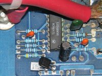
i am unable to power this amp up to even try and test voltages.I hooked up power to the amp including remote turn on and it fried a five amp fuse instantly.I'm getting continuity between the middle leg and the right leg on four transistors. They are the transistors in the upper left hand corner of this photo(its my actual amp).I can provide much better pics if needed.Will these four shorted transistors keep the amp from powering up?
If those transistors are shorted from pin 2 to pin 3, that would cause it to blow fuses. When you try to remove the clamps, the foam tape will make it difficult. Use this method (see attached image) and you'll be less likely to do any damage to the remaining transistors.
Attachments
It's not likely to cause any problems but you should probably replace the parts before powering it up. If you're lucky, you may have only one failed component. The rest may be OK. If some are still in good working order, it would be OK to power it up with only one of the four missing. After determining if there are other problems, all 4 transistors MUST be replaced. Mismatched transistors will reduce reliability.
The older orions wouldn't power up through a series power resistor (used to prevent further damage) so you will need to use a 10 amp fuse in the power line when doing initial testing.
To remove the transistors, apply enough new solder to allow heating all 3 terminals of the transistor at once (iron laying diagonally across the legs). The transistor will slide off of the pads when heated. This should take no more than 3-4 seconds for each transistor.
There is a stray black wire in this amp that I can't figure out what its use is.There are two larger gauge wires which appear to be the negative speaker outputs and then right next to them is a smaller black wire. Any idea what this wires purpose is?In the pic of that other guys amp it doesn't appear that his amp has this same wire.
In some of the older Orion amps, there was a black wire connected to the secondary power supply ground. It was supposed to help eliminate engine noise if you ran it to the head unit's ground. Engine noise was rarely a problem with the amps. When there was engine noise, there was typically some other problem.
well I've removed the clamp down bars and was very happy to see that my damaged parts were something easy to find.2N6491's i believe. Is it necessary to replace the 16 total output transistors so they all match or just the group of four that is bad?Would it even be beneficial to replace all of them or a waste of time?I did have one mishap when taking off one of the bars though. Check it out here . Not sure what that device is.It is a lm337t I think.The top of it just came right off with the clamp down bar.Will it be necessary to replace all four parts in that group or just the one that came apart?
It's not 'necessary' to replace any other transistors except the ones in parallel with the one that failed. I prefer to change all in the failed channel but that's your decision here. If you do a good job of replacing the 6491s and don't damage the board or pads, I'd suggest changing the 6488s in that channel also.
I'd leave the other channel alone.
You only need to replace the lone 337.
Did you remove the clamps like I suggested or did you remove them by prying between the clamp and the tab of the transistor. I've never seen a component come apart using the method I suggested.
When you replace the transistors, use desoldering braid (not from radio shack) to remove all of the old solder. Bolt the board back into the sink and set the transistors in place. Then solder the leads to the pads. If the leads don't quite touch the pads, you can either form the leads to touch or allow solder to bridge the gap (generally just a few thousandths of an inch). In some Orion amps, if you solder the transistors down to the board and then install everything in the sink, the pads will be pulled up when you replace the screws that hold the board down. If you solder them to the board when they are in place, there will be no stress on the pads or leads when everything is reassembled.
I tried your method and it worked great for the most part but I had a couple stubborn parts that wouldn't come off unless I pinned them down while trying to pull the bar off of them.Is a 40 watt iron too much for this type of work?I'm kinda scared it might get too hot and damage some other parts.
The wattage of the iron's not what's important. It's the temperature that's important. Some irons are simply heaters that run at full power. Others have temperature controls.
A standard (non temp controlled) 40 watt iron should not be too hot. Be sure the tip is shiny/clean and accepts solder well. If it doesn't, get a tin of tip cleaner from Radio Shack. It works wonders for all but the most worn tips.
When soldering, no operation (soldering/desoldering) should take more than 5 seconds. If you have to keep the iron in place longer than that, the iron isn't getting hot enough or you're not getting good heat transfer to the board. Applying new solder between the tip and the board will help promote heat transfer.
To make the job look nice, tack the tip of the center lead of each transistor in place. Make sure that they're all straight/perpendicular to the board and then solder them in place.
The 6488 is the complement to the 6491 and was used in many of their amps. The 2889s are not readily available and were likely rebadged 6488s (someone will correct me if that's not correct).
- Status
- Not open for further replies.
- Home
- General Interest
- Car Audio
- Old School Orion 2150 gx.I must repair this amp