ok this is an Audiobahn A18001DT that just died one day
so I took it to the local shop that sat on it for at least 5 weeks
now I'm out $25 bucks and not even sure he looked at it
after searching in vain for a better shop I decided to at least
look at it before sending it off to the factory repair shop $$$
at first glance everything appeared fine then I noticed a black
smudge near 1 of the FB31N20D mosfets? well upon a web
search I happened to find this site and tried to use the threads to guide me through the way to fix this ^@%@^% amp
sorry I'm very frustrated and rambling on
anyway I've relaced the 10 FB31N20D's- only the one was slightly
higher on the bench test 0.81 Ohms compared to 0.68 for the rest
I also checked the resistors nearby- all very consistant so I thought it would fire right up- wrong again- nothing but the protect light mocking my pain... back to the old forum board
I found this one helpful (NEW FETS INSTALLED, NO POWER) but
can't solve the problem of low voltage at the KA3525A PCM?
so here are my reading on the old DMM
PIN1: 0
PIN2: 5.03
PIN3: 0.01
PIN4: 0.18
PIN5: 2.25
PIN6: 3.44
PIN7: 2.24
PIN8: 0.37
PIN9: 3.37
PIN10: 0
PIN11: 4.09
PIN12: 0
PIN13: 9.86
PIN14: 4.09
PIN15: 9.86
PIN16: 5.03
my battery (with 5amp fuse) read 11.86
any ideas?
I read about the input drivers but I'm not sure which is which
do they look similar to mosfets?
I've tried back tracing but this thing seems overly complicated
have not seen any 2sa1266
I'm new and learned what I know mostly off of here
I wish had a camera so I could post a picture
thanx for replying
do they look similar to mosfets?
I've tried back tracing but this thing seems overly complicated
have not seen any 2sa1266
I'm new and learned what I know mostly off of here
I wish had a camera so I could post a picture
thanx for replying
Something is very strange about the numbers you posted. Pin 8 is the soft-start pin and is generally near 5v after the soft-start cap has fully charged. It's very low and I'd expect the IC to be off (producing no output on pins 11 and 14) but there is clearly some activity on the outputs.
The drivers are likely 2sa1023s ans s2c1027s. If I'm not mistaken, there are 8 drivers (4 for each set of PS FETs).
With the amp powered up, what is the DC voltage on pin 1 of the power supply FETs (only post one value if they're close). They should be near the voltage on the outputs of the 3525. You can follow the drive voltage from the outputs of the 3525 to the 3rd pin of the drivers and then from the first pin of the drivers to the outputs.
The 3525 on many of this style amp is powered via an NPN transistor. This is less efficient than using a PNP transistor and the voltage at the IC will be lower than you'd expect.
Just a heads up on buying those driver transistors if that indeed turns out to be the problem. I have not been able to find a place to buy those KEC parts A1266 1023 1027 etc but if you go to fairchild semiconductors website and use the cross reference they have some much less expensive parts that will substitute for those drivers. I have used them personally so I know they work as subs.
Here's the link:
http://www.fairchildsemi.com/crossref/crossref.jsp
I look them up with "Begins with" KTA1266 KTA1023 KTC1027 KTC3198 etc... Most common drivers and what not in car audio amps I have seen thus far.
Then go to your choice (mine is Mouser) to buy the fairchild parts, for probably much less than the KEC parts.
If someone has a good source for the KEC parts preferebly with online ordering and inventory, please email me sales@db-r.com
Perry Babin said:Something is very strange about the numbers you posted. Pin 8 is the soft-start pin and is generally near 5v after the soft-start cap has fully charged. It's very low and I'd expect the IC to be off (producing no output on pins 11 and 14) but there is clearly some activity on the outputs.
The drivers are likely 2sa1023s ans s2c1027s. If I'm not mistaken, there are 8 drivers (4 for each set of PS FETs).
With the amp powered up, what is the DC voltage on pin 1 of the power supply FETs (only post one value if they're close). They should be near the voltage on the outputs of the 3525. You can follow the drive voltage from the outputs of the 3525 to the 3rd pin of the drivers and then from the first pin of the drivers to the outputs.
The 3525 on many of this style amp is powered via an NPN transistor. This is less efficient than using a PNP transistor and the voltage at the IC will be lower than you'd expect.
ok (if I understand) I do have four a1023 and four a1027
pins 1 (I assume lefthand facing print) on all are 4.36
pins 3 (righthand) are 3.91
uncertain if drivers and power supply FETs are one and the same
running low on 5 amp fuses LOL

The power supply FETs are clamped to the heatsink (likely IRFZ44s). The drivers boost the output current capability of the 3525 IC. The IC can't reliably drive that many FETs alone.
In place of fuses, you may want to use a current limiting resistor or an auto headlamp. The H6054 works pretty well. I use 2 ohm resistors. The large tubular ceramic 100w are the most foolproof. With fuses, they blow and you know there is a problem. With resistors (or the headlamp) you have to be more aware of the temperature of the components and the current being drawn (your power supply would need to have an amp meter). There are a few amps that won't power up through the resistor/headlamp but most will. Many amps pulse on/off a few times (likely low voltage protection in action) before they stay on.
In place of fuses, you may want to use a current limiting resistor or an auto headlamp. The H6054 works pretty well. I use 2 ohm resistors. The large tubular ceramic 100w are the most foolproof. With fuses, they blow and you know there is a problem. With resistors (or the headlamp) you have to be more aware of the temperature of the components and the current being drawn (your power supply would need to have an amp meter). There are a few amps that won't power up through the resistor/headlamp but most will. Many amps pulse on/off a few times (likely low voltage protection in action) before they stay on.
Perry Babin said:The power supply FETs are clamped to the heatsink (likely IRFZ44s). The drivers boost the output current capability of the 3525 IC. The IC can't reliably drive that many FETs alone.
In place of fuses, you may want to use a current limiting resistor or an auto headlamp. The H6054 works pretty well. I use 2 ohm resistors. The large tubular ceramic 100w are the most foolproof. With fuses, they blow and you know there is a problem. With resistors (or the headlamp) you have to be more aware of the temperature of the components and the current being drawn (your power supply would need to have an amp meter). There are a few amps that won't power up through the resistor/headlamp but most will. Many amps pulse on/off a few times (likely low voltage protection in action) before they stay on.
ok the IRFZ44 (16 of them) had 4.29 volts on pin 1 (lefthand)
11.38 on middle and zero on pin 3
the fuses were blowing because of my unsteady fumbling
I put black tape on my probe and rubbed off the tip- haven't used
up any more fuses
The amp should be producing rail voltage. Check the DC voltage on the ~1.5" inductor (the one that is not paired with any others - likely copper and green colored windings). Check all 4 terminals. At least one should have positive rail voltage and one should have negative rail voltage. These inductors have caused the failure of many amps. Check for broken solder connections and broken windings. Also look for any 'dust' where the windings meet. It's generally found where the terminal winding passes over the top of the coil. If there is colored dust (the color of the enamel insulation), the inductor may be failing or has possibly failed. Twisting the inductor slightly while the amp is on can help you find intermittantly shorted problem.
While you're checking the inductors, check the two next to the IRFB31n20s. They have the same problem.
While you're checking the inductors, check the two next to the IRFB31n20s. They have the same problem.
This amp sounds similar to the amp I just got done working on, a Planet Audio TT2250D uses the exact same, 10 31N20d's and 16 IRFZ44's.
A problem I had, after installing all new fets, was that when I soldered in one of the new 31N20d's, the solder ran through the via, and puddled up on the other side of the board on the leg of the FET. Which in turn shorted itself to a trace on the board, just under that leg. Caused the amp to go into protect, but did not hurt anything. Check all your soldering very well.
A problem I had, after installing all new fets, was that when I soldered in one of the new 31N20d's, the solder ran through the via, and puddled up on the other side of the board on the leg of the FET. Which in turn shorted itself to a trace on the board, just under that leg. Caused the amp to go into protect, but did not hurt anything. Check all your soldering very well.
Perry Babin said:The amp should be producing rail voltage. Check the DC voltage on the ~1.5" inductor (the one that is not paired with any others - likely copper and green colored windings). Check all 4 terminals. At least one should have positive rail voltage and one should have negative rail voltage. These inductors have caused the failure of many amps. Check for broken solder connections and broken windings. Also look for any 'dust' where the windings meet. It's generally found where the terminal winding passes over the top of the coil. If there is colored dust (the color of the enamel insulation), the inductor may be failing or has possibly failed. Twisting the inductor slightly while the amp is on can help you find intermittantly shorted problem.
While you're checking the inductors, check the two next to the IRFB31n20s. They have the same problem.
ok the terminals read +0.49, -0.49, +0.4, -0.4 on (copper/green)
all appeared well no dust/discoloration
twisting had no effect- should I remove it for inspection
and resolder? should the voltage be higher?
the others (heavy gauge wire) were at zero so I reversed my
probes to check for gound and got 0.08 again twisting had no effect. I have no idea what all this means
thank you in advance for your patience with this beginner
dB-r said:This amp sounds similar to the amp I just got done working on, a Planet Audio TT2250D uses the exact same, 10 31N20d's and 16 IRFZ44's.
A problem I had, after installing all new fets, was that when I soldered in one of the new 31N20d's, the solder ran through the via, and puddled up on the other side of the board on the leg of the FET. Which in turn shorted itself to a trace on the board, just under that leg. Caused the amp to go into protect, but did not hurt anything. Check all your soldering very well.
I was very careful while placing the FETs and resoldered from the
bottom plus there are fairly thick rubber isolators under the board
You should have at least ±50 volts on two of the legs of that inductor.
Check for broken leads on the rectifiers (on the sink next to the copper/green inductor).
Check AC (not DC) voltage across the primary windings (one lead on the center tap leg and one lead on an outer leg). Do the same on the secondary.
Check for broken leads on the rectifiers (on the sink next to the copper/green inductor).
Check AC (not DC) voltage across the primary windings (one lead on the center tap leg and one lead on an outer leg). Do the same on the secondary.
Perry Babin said:You should have at least ±50 volts on two of the legs of that inductor.
Check for broken leads on the rectifiers (on the sink next to the copper/green inductor).
Check AC (not DC) voltage across the primary windings (one lead on the center tap leg and one lead on an outer leg). Do the same on the secondary.
ok, I had to use an analog meter for AC, on the copper/green
inductor, if I read correctly one side was 300 the other 240
could't SEE anything wrong with the rectifiers
(two FMU34S, two FMU34R) not sure how to test these

I should have been more clear. I wanted you to check the AC voltage on the main power transformers, not the inductor. The terms primary/secondary winding and center-tap don't apply to inductors.
While the rectifiers are not clamped down, push them gently to each side while closely watching the point where the leads enter the body of the component. Sometimes they break inside the body and you have to look very closely to see that the lead isn't moving with the body. Don't push too far, you don't want to break the leads.
It's unlikely that the rectifiers are defective other than having the leads broken. If you want to check them, set your meter to diode check and check them like a normal diode (using the symbols on the front of the rectifier to know how the internal diodes are wired). This is best done out of the board but there's a lot of heavy copper on the pads so you'll need a good iron to get them out.
Perry Babin said:I should have been more clear. I wanted you to check the AC voltage on the main power transformers, not the inductor. The terms primary/secondary winding and center-tap don't apply to inductors.
While the rectifiers are not clamped down, push them gently to each side while closely watching the point where the leads enter the body of the component. Sometimes they break inside the body and you have to look very closely to see that the lead isn't moving with the body. Don't push too far, you don't want to break the leads.
It's unlikely that the rectifiers are defective other than having the leads broken. If you want to check them, set your meter to diode check and check them like a normal diode (using the symbols on the front of the rectifier to know how the internal diodes are wired). This is best done out of the board but there's a lot of heavy copper on the pads so you'll need a good iron to get them out.
I double checked the rectifiers- they look ok
now, if I somehow got it right, the primary side of the two large
transformers was 24 volts AC the secondary was about 150 AC
I've been reading as much as I can but still have A LOT to learn
please bear with me I really want to fix this thing
still in protection limbo
does anyone have any ideas where to check next?
it still has a low voltage issue preventing it from turning on
I can't figure this thing out. do I need to replace something else?
I will keep at this |#%@^%# until it works again
PLEASE help me I am stuck
does anyone have any ideas where to check next?
it still has a low voltage issue preventing it from turning on
I can't figure this thing out. do I need to replace something else?
I will keep at this |#%@^%# until it works again
PLEASE help me
I am stuckIf you have 24vac on the primary, the amp's power supply is operating. The 150v on the secondary confirms this. The output of the transformer goes to the rectifiers then to the inductor and from there to the filter caps. The input to the rectifiers is AC. The output is DC with a lot of ripple. The output of the inductor is DC (ripple is filtered by the caps).
Measure the AC and DC voltages on the output transistors while it's in fully powered up. Black lead on the secondary center tap. DO NOT allow your probe to slip while checking the voltage. If this section is operating, you should have rail to rail oscillation on one pin of half of the outputs and rail to rail oscillation on 2 pins of the other half of outputs. The pins with no oscillation will have pure DC. Do this with no signal input.
Again, using the secondary center tap for the reference (black lead), measure the DC voltage on pins 4 and 8 of the 8 pin op-amps. You should have ±15v on them.
ok I tested DC on the IRFZ44N output transistors?
using the center pin as ground I got -11.3 volts (bat)
the other side was -5.7 (half)?
using AC I got maybe 9 volts on one side and slight negative reading on the other of the IRFZ44N with black on center
as far as the 8 pin op-amps I got 11.3vdc on pin 4 and 5.7 on 8
obviously not what I was hoping to see but no slipped probes
this time
I am still not sure if I followed your instructions correctly
this thing has been collecting dust because its always too cold in the garage and frankly I was sick of it mocking my painful lack of knowledge everytime I worked on it
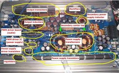
Look at the green arrows on the attached photo. They point to the center taps where two heavy windings go to the same area of copper. Use that for your reference (touch your black lead there).
The Z44s are the power supply transistors, not the output transistors.
Study the photo.
Re-measure the voltage on all of the points (outputs, op-amps...).
Ask questions if you're unsure about anything. Don't be embarrased. We were all clueless at one point.
The Z44s are the power supply transistors, not the output transistors.
Study the photo.
Re-measure the voltage on all of the points (outputs, op-amps...).
Ask questions if you're unsure about anything. Don't be embarrased. We were all clueless at one point.
Attachments
- Status
- This old topic is closed. If you want to reopen this topic, contact a moderator using the "Report Post" button.
- Home
- General Interest
- Car Audio
- my first broken amp... need help