Hello
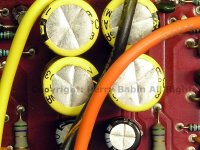
Like a moron I didnt pay attention to which way the negative side of a few of the 6 capacitors in the center of the amp face well there are 4 1000uf 50V caps and 2 1000uf 25 volt caps I know the 2 center 1000uf 50 volt caps the negative sides of the caps face each other but the other 4 I am not sure , I looked on amp guts and see a 275 sx and my 280GX has the same layout but not sure if those caps are situated the same and I cant make out the polarity on 1 of them in that picture can anyone please help me. again mine is the 280GX and on ampguts that 275sx is the same board I have minus the eq functions I know some other 280GX amps the board layout is different.
thank you
1 more question
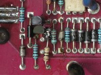
ther are on each side of the amp by where the power and ground go in and driectly oposite on the other side of the amp a mirrior image of 1 mps A06 and mps A 56 there is a resistor that connects to 1 of the outside legs of the mps A56 and on both sides the resisitor is burned beyond recognition sinc I see you have a pic of the capaitors, would you or anyone know the value of these 2 resistors as they are burned beyond the ability to tell.
Thanks Again
redblaze
Ok im stuck I replaced all power supply transistors with IRF2807
and replaced all 6 1000uf 50V caps , the 2 1000uf 25V caps I replaced the rectifiers with same , I replaced the 2N6488's with D613's and the 2N6491's with same, the a06 I used A42's and the a56's with A92's and when I apply power to test it the light turns on for a split second and then shuts off my powersupply , could this be the opamp ? what could i be missing by chance ?
thank you for your help
redblaze
P.S.
If your power supply is rated for more than 5-10 amps, you should have a current limiter or relatively small fuse (~10 amps) in series with the main power wire.
You should also have the transistors clamped down while troubleshooting. When there is a fault, they can overheat and fail within seconds.
If your power supply is rated for more than 5-10 amps, you should have a current limiter or relatively small fuse (~10 amps) in series with the main power wire.
You should also have the transistors clamped down while troubleshooting. When there is a fault, they can overheat and fail within seconds.
I took out the rectifiers and put a 3amp fuse inline , the fuse did not blow and the amps powersupply started to sing (screech) , before the 3amp fuse would blow right away and without the fuse it shut the powersupply down ( yes current limiting) , but again without the rectifiers all seems ok but no power light , but I suppose this is because of the rectifiers not transferring power to the amp side ? Just the powersupply is turning on ?
Thank you for helping me
redblaze
Thank you for helping me
redblaze
If any of the power supply transistors are getting hot when the rectifiers are out, there may be a problem with the drive circuit. This is when a scope is very nice to have. You can look at the waveform and determine if there is a problem.
You're right, the removal of the rectifiers broke the connection to the audio section. The problem is very likely in the audio section.
Are you 100% sure that you have the caps installed properly?
You need to buy a current limiter. An H6054 headlamp will work. Use the high beam connections. Insert it in place of the fuse.
With the limiter in place, power up the amp and measure the voltage across each of the emitter resistors. There should essentially be no voltage across the resistor. 0.001 volt is common. If you find some that are 0.05 (for example) and the rest are essentially at zero volts, that will tell you where excessive current is flowing.
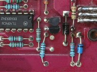
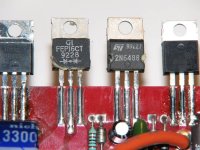
I will most deffinately check the caps again , But I know now that the square solder points are positive and round negative thats how i have them soldered in , the pic you have of the caps is exactly the same layout on my 280, I did check to see if the the powersupply transistors were getting hot or even warm and they werent they stayed very cool, by chance can you post a pic of the rectifier sections , I want to make sure I have them in the right order , right after the last powersupply transistor I have the FEP16CT then after that the LM340T15 per side .
also are they dual - or dual + I only ask to check and see if anyone else may have replaced wrong parts in the amp and i just followed them , the FEP16CT's are dual + , originally after the FEP16CT a L7815CV was used but the recomended cross reference was to use the LM340T15 hopefully this is ok.
I will test the Emitter resisotrs asap
thank you
redblaze
well I decided to test putting 1 rectifier in at a time and test the amp , I have 1 channel working , if you are looking at the amp RCA's facing to you the right side is the side that is working and also has the power light , the powersupply quit screeching aswell , if i put the other rectifier back in and remove all outputs on the left side replacing them 1 by 1 and testing the amp will that work to pinpoint the bad parts aswell ?
Both rectifiers must be in place for either channel to operate properly.
To make sure that there is no confusion, the rectifiers are the components with the diode symbols.
The 2n6488 and 2n6491 next to the rectifiers are the regulators. I'm not sure why you have 340t15 regulators. If the board looks precisely like the 225, the components should be the 88 and 91.
If an output is defective, it should be easy to find with an ohm meter.
Have you checked to see if any of the outputs are shorted?
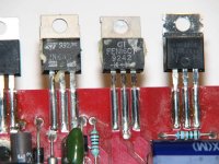
I just did , none of the outputs are shorted but I pulled them from the board again to test them , I will replace them and see if when I test them installed I get a short. per side if you start from powersupply to front of the amp on 1 side you have 5 IRF2807 then the FEP16CT , the LM340T15, 3 2N6488 (in this case the D613 replaced the 6488's) a 1 inch space then 3 2N6491's
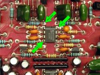
Can you make a voltage measurement?
Amp on
DC volts
Black lead where indicated in the photo
Red lead on pins 4 and 8
Pin 8 should have positive 15 volts (approximately). Pin 4 should have negative 15 volts.
If that's not what you have, turn the amp off and measure the resistance between pin 8 and the third leg of the 2n6488 next to the rectifier (as shown in the previous photo). Do the same between pin 4 and the third leg of the 2n6491. Both should read ~0 ohms.
The lm340 regulators are both positive regulators. From the description of the parts layout, your amp seems to be exactly like the amp I have here and there should be no lm340 regulators.
Attachments
on this 280GX on 1 side you have your powersupply transistors then 1 FEP16CT originally there was a L7815CV but when the guy at Parts Electronics looked it up the part it referred was the LM340T15 to take the place of the L7815CV, is this correct or should i pull the LM's and get better parts ?
I just tested the L7815CV's and they tested ok so I put those back in and the amp still did the same thing  well I will let it go for tonite and start over tomorrow , I wil do everything you told me to do earlier checking the Emitter resistors, I will try to get a good camera to take a pic of the board layout I have , the power supply and 6 capacitors in the center of the amp look the same as the 275 but moving to the RCA section it starts to get much different aswell as the transistor layout .
I do greatly appreciate your help
redblaze
well I will let it go for tonite and start over tomorrow , I wil do everything you told me to do earlier checking the Emitter resistors, I will try to get a good camera to take a pic of the board layout I have , the power supply and 6 capacitors in the center of the amp look the same as the 275 but moving to the RCA section it starts to get much different aswell as the transistor layout .I do greatly appreciate your help
redblaze
- Status
- This old topic is closed. If you want to reopen this topic, contact a moderator using the "Report Post" button.
- Home
- General Interest
- Car Audio
- Orion 280GX