If there was a 7815 on one side, there should have been a 7915 on the other side. The 7815 is a positive regulator. The 7915 is a negative regulator. The 340 can replace the 7815 but not the 7915.
If the originals were actually 78/79-15s, the third leg of the 7815 should be connected to pin 8 of the op-amp in the photo. The center leg would have been connected to the point where I asked you to connect the black lead. For the 7915, the first leg would be connected to the point where I asked you to connect the black meter lead.
I don't think the quality of the part is the problem. I think you have the wrong parts.
well 1 is a 7815 and the other is a 78 or 79 I cant really make out the numbers any longer on 1 of them , anyhow i put them back in the amp and swapped each to the other side testing the amp each time making sure to be safe not to ruin any of the new parts and with the 1 rectifier in and 1 out the amp functions , but with both rectifiers in , it blows the 3amp fuse and turns off the powersupply, all the IRF2807 are cycling some get warm then cool down then others on the other side get warm then cool down none of them get to hot.
Since there is 1 negative and 1 positive regulator should there be 1 dual positive and 1 dual negative rectifier ? both rectifiers are dual + that I have so maybe this is the problem ? so basically if this is the case on 1 side there will be a negative regulator with a dual - rectifier and then on the other a positive regulator with a dual + rectifier ?
Since there is 1 negative and 1 positive regulator should there be 1 dual positive and 1 dual negative rectifier ? both rectifiers are dual + that I have so maybe this is the problem ? so basically if this is the case on 1 side there will be a negative regulator with a dual - rectifier and then on the other a positive regulator with a dual + rectifier ?
well upon looking at the rectifier photos you sent there is a dual + on 1 side and a dual - on the other , so am I correct that on this 280 there is a - regulator and dual - rectifier on 1 side and a +regulator and dual + rectifier on the other ?
I hope thats it , it would make sense that the amp works with 1 of them out , with both in they just fight aginst each other causing a short.
I hope thats it , it would make sense that the amp works with 1 of them out , with both in they just fight aginst each other causing a short.
You should never swap parts that do not have the same function. You said you swapped rectifiers and regulators. If you swap rectifiers, you may damage lots of components because it applies reverse voltage to all components connected to the output of the rectifiers.
Installing the regulators in the wrong location can also cause problems downstream but will likely damage the regulators.
There are complex circuits inside the regulators. You can't check them like you can rectifiers or transistors. You can determine if they're shorted from pin to pin but if they're not shorted, that doesn't mean that they're in proper working order. I'd assume that both regulators are defective because they have likely been subjected to reverse voltage.
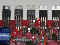
You're right. On one side, you have a positive rectifier. That sends all of the positive output of the power supply to the positive rail caps. Next to it is the positive regulator. In the amp I have here, the regulator consists of a 2n6488 and various other components. If your amp uses an L7815 for the positive regulator, it requires no other components. The other side has the negative rectifier and regulator.
Do this... Measure the resistance from the first leg of the negative regulator to the middle leg of the positive regulator. Also measure the resistance from either of those legs to the point where I suggested you connect the black meter lead in a previously posted photo (with the green arrows). Let me know the results.
Installing the regulators in the wrong location can also cause problems downstream but will likely damage the regulators.
There are complex circuits inside the regulators. You can't check them like you can rectifiers or transistors. You can determine if they're shorted from pin to pin but if they're not shorted, that doesn't mean that they're in proper working order. I'd assume that both regulators are defective because they have likely been subjected to reverse voltage.
You're right. On one side, you have a positive rectifier. That sends all of the positive output of the power supply to the positive rail caps. Next to it is the positive regulator. In the amp I have here, the regulator consists of a 2n6488 and various other components. If your amp uses an L7815 for the positive regulator, it requires no other components. The other side has the negative rectifier and regulator.
Do this... Measure the resistance from the first leg of the negative regulator to the middle leg of the positive regulator. Also measure the resistance from either of those legs to the point where I suggested you connect the black meter lead in a previously posted photo (with the green arrows). Let me know the results.
in this 280 I had 6 2N6488 and D613's were recomended as replacements , and it also had 6 2N6491 and I replaced those with original 6491's now there were 2 rectifiers 1 burned beyond recognition so I assumed that both were the FEP16CT's dual positive and there were 2LM7815's but 1 the writing was faded so I agree it is probably a 7915, each side had a rectifier and a regualtor , but you said if it had a 7815 no other components were required ? meaning I shouldnt have a rectifier and the 7815 regulator ? well what I need to do is go to the electronics shop and get another + and - regulator and a dual - FEP , since they may be damage I will get 4 new parts 2 regualtors and 2 rectifiers and a a limiter , now I am determined to get this amp working, I will get pics to show you aswell so you can make sense of my mess ")
Thank you again Perry
Thank you again Perry
When I said that no other components were needed with the 7815, I meant that no others were needed for the regulator to regulate the voltage. When the 2n6488/91 is used as part of a regulator, they need a voltage reference. The reference is generally produced by a resistor and a zener. The 88/91 can't be a regulator without the other components. The 7815 can regulate without other components.
Both regulators and rectifiers are needed.
Please do this... Measure the resistance from the first leg of the negative regulator to the middle leg of the positive regulator. Also measure the resistance from either of those legs to the point where I suggested you connect the black meter lead in a previously posted photo (with the green arrows). Let me know the results. Since we don't know the condition of the regulators, it would be best if they were removed when doing this. Make sure that there are no solder bridges between the solder pads for the regulators.
I will do the measurements , my only problem is I do not know which side the - and + regulators went on since I had it wrong in the first place, from the amp you took the pics of can you give me an idea of which side was - and which was + , I also went and bought 2 new regulators and rectifiers just incase the otheres were bad. now do both the - regulator and - rectifier go on the same side and both the +'s on the same side ?
Sorry for the confusion on my end here , I bought the amp off ebay and it was in much worse shape inside than what was described.
Sorry for the confusion on my end here , I bought the amp off ebay and it was in much worse shape inside than what was described.
my problem is that when I took the amp appart ALL of the transistors were burned except for the 7815 and 7915 and i thought they both were 7815 so i do not know which side was which unfortunatley and only 1 rectifier was intact and again I thought both rectifiers were + so I do not know which side it came from , would you know or is there a way to tell on the amp itself ? I will try to follow the positive side of the caps to the rectifier pads , or if you can tell me which side is which from the pics you have ?
I found the correct sides for the regulators and the rectifiers , I tested the voltage from the first leg of the + regulator to pin 8 and I get 14.3 volts DC I left the fuse in but pulled the headlamp and the amp now lights up as normal and does not blow the 3amp fuse , I have not used the new parts ,I used the old 7815 and 7915 , I applied a signal and the amp seems to be working correctly both gains operate correctly , the torroid gets hot but that flucuates but at high output it stays at a stable temperature, no parts are damaged at all and no overheating has occured but I will leave it off untill I hear back from you Perry and what your next suggestion will be , I dont want to trust it just yet there is a lot of work in this amp.
Something's not quite right. The first leg of the negative regulator and the middle leg of the positive regulator are the ground pins. There should essentially be a direct connection (~zero ohms) between them and the point labeled as 'black lead' in the photo.
Measure the resistance between the points below. If you get 0 ohms for each pair of test points, your amp should not have 78/79-15 regulators. It should have transistors as those shown in the photos.
Measure the resistance between the points below. If you get 0 ohms for each pair of test points, your amp should not have 78/79-15 regulators. It should have transistors as those shown in the photos.
Attachments
ok on the first leg and middle leg I get 0ohms I was on the wrong leg of the - regulator and in the test you show for me to do in the last picture from rectifier to regulator , now where you have a 6488 I have a 7815 and from middle leg to middle leg I get .614 and this is with no power at all applied to the amp , I get the same reading across the small diode aswell .614
In my previous post, I was looking for 2 measurements. The way you measured it doesn't tell me anything. The 0.614 reading could be any number of things. I wanted these measurements to verify the circuit layout. I've never seen an orion amp with 78/79-15 regulators. If you would have read 0 ohm with the meter leads connected as shown in the photo, I would have known that the amp should NOT have had the 7815.
It's not important now if you have zero ohms from pin 1 of the 7915 to pin 2 of the 7815.
It's not important now if you have zero ohms from pin 1 of the 7915 to pin 2 of the 7815.
My board layout is slightly different then the photo , to be honest I have never seen an orion amp like this either , I looked at a pic of what was a replacement board for a 280GX and my 280 GX looks nothing like it , orcourse it is an orion board inside there is no mistaking that , but my board looks like maybe an early version of the 275sx without the EQ boost section. I have a fluke MM I had the settiongs on 2kohms and those readings are what I got , so I think I had the fluke set wrong ? I will get pics of the board and post them. I will deffinatley give you the readings I get when I do it correctly. I just need to get you pics. but yes I do get 0ohms I tried it again from the 78/79-15.
Why do you suppose they have a 78 and 7915 ?
Why do you suppose they have a 78 and 7915 ?
I wanted to add my 2 cent also but, i have a 2150 gx and it uses the 78/79-15 regulators and the amp i got would be good to add pictures on amp guts but, not sure how to get it up there.I have lots of pictures that guy doesn't have that would help others.The gx model has many odd facts about it and i see why they didn't carry that model long.
- Status
- This old topic is closed. If you want to reopen this topic, contact a moderator using the "Report Post" button.
- Home
- General Interest
- Car Audio
- Orion 280GX