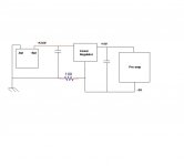
I'm in the process of building a preamp for my vehicle. I've built a prototype, and I'm having problems with noise. Attached is a block diagram of the system. In the block diagram the voltage regulator is shown separate from the the preamp, but in reality everything after the battery is on the same PCB. During initial testing the 100 Ohm resistor shown was actually 0 Ohms. This could be the reason why I was picking up noise. Now, I have replaced the 0 Ohm resistor with a 100 Ohm resistor as shown in the diagram, but I haven't tested it out for noise yet.
Please give suggestions/comments about this design. My main concern is with the power supply portion (linear regulator) and reducing/eliminating noise.
Regards,
Tom
Please give suggestions/comments about this design. My main concern is with the power supply portion (linear regulator) and reducing/eliminating noise.
Regards,
Tom
Attachments
Hi Tom,
That will not make you happy. What you really should have is a supply that transformer couples, you can get a bipolar supply at the same time. The 100 R resistor should not have any current running through it. It is used to break ground loops.
So try to make a little inverter that will allow you to break the supply ground.
-Chris
Chris,
Thanks for the reply. In order to do what you are talking about, am I going to have to build a switcher? I really wanted to stay away from that and make the PS design as simple and cheap as possible.
*Edit* But then again I do want a clean audio signal, so if I must build something different thant what I currently have I'm up for it.
*/Edit*
Isolated Switcher
Tom,
Check out these links:
http://cache.national.com/ds/LM/LM2577.pdf
http://cache.national.com/ds/LM/LM2587.pdf
It's the National Semiconductor SimpleSwitcher series of switcher ICs. Using an LM2577 - 3A chip (or an LM2587 - 5A chip), you can make a nice bi-polar output isolated flyback switcher that is reasonable simple (hence the name SimpleSwitcher ), and excellent in performance. Of particular interest to you would be p.14 of 27 on the LM2587 Datasheet.
Cheers,
Steve
Tom,
Check out these links:
http://cache.national.com/ds/LM/LM2577.pdf
http://cache.national.com/ds/LM/LM2587.pdf
It's the National Semiconductor SimpleSwitcher series of switcher ICs. Using an LM2577 - 3A chip (or an LM2587 - 5A chip), you can make a nice bi-polar output isolated flyback switcher that is reasonable simple (hence the name SimpleSwitcher
), and excellent in performance. Of particular interest to you would be p.14 of 27 on the LM2587 Datasheet.Cheers,
Steve
Steve,
Thanks for the input. So, I could basically take the circuit in figure 11, then just isolate the grounds and use an opto-isolator for the feedback to the control IC? What if instead of an opto-isolator I use a 100 Ohm resistor to separate primary and secondary grounds? Or is the opto-isolator the better (cleaner) approach?
Regards,
Tom
How elaborate is the preamp (crossover, multi-band EQ...)?
You mentioned that you wanted to do it as cheaply as possible. Price range?
A transformer based switching power supply is probably the best solution (depending on how you define best). It gives you isolation and a bipolar supply as mentioned. A capacitor based switching supply can give you the bipolar output but not the isolation.
To get isolation from the chassis ground, you can use a transformer (ground loop isolator) to break the ground loop. If you want to make a slightly more complex preamp, you can build in a circuit (op-amp based) that will cancel the noise that would be associated with ground loops.
Old PAC devices (simple crossovers and such) grounded the devices via the shield ground of the head unit. To get the same benefits, you can ground your preamp directly to the head unit's case. Since there would be no difference of ground between the head unit and the preamp, there should be no ground loop.
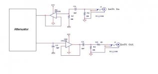
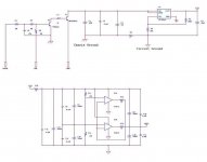
The preamp circuit is actually an attenuation circuit. I just called it a preamp to simplify things. The input signal is AC coupled and and then biased to Vcc/2 using an artificial ground circuit. I've attached a drawing showing the Linear Regulator and the Artificial ground. At the time of the design I was hoping that separating the chassis ground and circuit ground with a 100 ohm resistor would be enough to bring the signal above the noise level.
I've decided to change to the switching power supply. If I do that I can eliminate the Linear Regulator and the artificial earth. I'm hoping in the end the cost to build the switcher will be about the same as the linear IC and artificial ground, and I'll get better results.
Regards,
Tom
I've decided to change to the switching power supply. If I do that I can eliminate the Linear Regulator and the artificial earth. I'm hoping in the end the cost to build the switcher will be about the same as the linear IC and artificial ground, and I'll get better results.
Regards,
Tom
Attachments
Tom,
That's about it. I agree with Perry that you MUST use a transformer for true ground isolation to get the desired noise reduction.
Try this link at National on Isolated SimpleSwitcher PSUs:
http://www.national.com/an/AN/AN-1095.pdf
and this one on a three-output LM2577-based isolated DC-DC converter.
http://www.national.com/an/AN/AN-777.pdf
In it, the two bipolar voltages are (+/-7.5V). For greater headroom, increase the turns using the calculations there to get (+/-12 to 15V).
Good info there, and I have to imagine theae were done specifically with audio applications in mind.
Tom,
An L-C filter is a good idea. I would cross-couple the windings of both the (+) and (-) outouts together (opposite phase, of course) to provide for better cross-regulation in the event of sudden input voltage changes or output current demands. This should attenuate the 100kHz switcher noise present to almost undetectable levels. Also, if you pop open your typical AT or ATX PSU, you will fing that the BIG yellow/white multi-winding toroid in the output section does this.
Even better, do this: L-C-L-C for both (+) and (-) buses, where the first Ls are the cross-coupled inductors, and the second Ls are individually wound.
- Status
- This old topic is closed. If you want to reopen this topic, contact a moderator using the "Report Post" button.
- Home
- General Interest
- Car Audio
- Preamp Power Supply Suggestions