who actually designed the original amps, back to the digital reference series? i think this guy deserves alot of credit, but never knew who actually designed them.
how did orion solder the fets/transistors/diodes onto the pcb's back then? reflow?..ya know, the entire leg is soldered to the board, instead of the usual solder spot at the end of the leg...
and
how do you measure the resistance of the isolated resistors? the long black ones with 9 pins...
how did orion solder the fets/transistors/diodes onto the pcb's back then? reflow?..ya know, the entire leg is soldered to the board, instead of the usual solder spot at the end of the leg...
and
how do you measure the resistance of the isolated resistors? the long black ones with 9 pins...
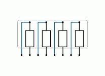
The resistor networks have 8 pins. There are 4 resistors. All 4 resistors have the same value unless the network was custom manufactured. The attached image shows how they're laid out.
As with any resistors, to get reliable readings, they need to be removed from the circuit.
As with any resistors, to get reliable readings, they need to be removed from the circuit.
Attachments
would it be ok too use regular resistors in there place? how would i go about finding out the tolerance? or would they just have used the tightest tolerance?
do you know what type of soldering technique they used to solder the fets/transistors onto the pcb...?
dont think they were soldered one by one, it wouldnt be consistent...its been baffling me for the longest time
do you know what type of soldering technique they used to solder the fets/transistors onto the pcb...?
dont think they were soldered one by one, it wouldnt be consistent...its been baffling me for the longest time

You can replace the networks with discrete resistors but unless they have failed, there is really no benefit. If you can find the datasheet for the resistors, it will tell you the tolerance.
I don't know the method they used. Getting the transistors placed consistantly is easy if you use a jig. Getting the solder connections to be consistent wouldn't be easy unless they used reflow techniques. I'm not sure what was possible when those amplifiers were introduced.
I don't know the method they used. Getting the transistors placed consistantly is easy if you use a jig. Getting the solder connections to be consistent wouldn't be easy unless they used reflow techniques. I'm not sure what was possible when those amplifiers were introduced.
- Status
- This old topic is closed. If you want to reopen this topic, contact a moderator using the "Report Post" button.
