Hey guys,
I have a 'boss audio rip 896' that i hooked up wrong; I hooked up the power to the gnd and the gnd to the power. I saw a long zap...I hooked it up correctly and the protection light keeps coming on.
I opened up the amp and tested the MOSFETs BJTs and all other transistors on the sides. All of them are okay..none are melted at all ..and all test correctly with the diode check on my digital meter.
I next tested the reverse polarity protect diodes..those were fine.
I tested the input filtering caps and those seem to be fine also.
I am totally lost now on what to check. I want to believe its the temp sensor (thermister / thermoresistor)..or maybe even the logic chip (or op-amp or w.e that chip is, 's494p').
What fully confuses me is why the reverse polarity path didnt protect the rest of the circuit. The path goes through the diodes and directly to the fuses... but neither blew.
PLEASE HELP!
tj
Hi tjmehta,
If everything but the power was hooked up and you hooked up positive first, you burned the ground traces or resistor between the signal ground and power ground. It is possible to cook a heat unit that way, or crossover (or all of it really).
Check with an ohmmeter first. I'm hoping it was just the resistor that is commonly used.
-Chris
i tried to attach pics to my previous posts...but i dont think it worked
so i posted them on my website ::
http://www.prism.gatech.edu/~gtg158w/gndpic.jpg
http://www.prism.gatech.edu/~gtg158w/gndpic1.jpg
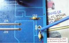
(not the cap being tested)
If u can see the numbers...it says C51..C=cap
is that the right point im looking at though..or where should i look?
thanks
so i posted them on my website ::
http://www.prism.gatech.edu/~gtg158w/gndpic.jpg
http://www.prism.gatech.edu/~gtg158w/gndpic1.jpg
(not the cap being tested)
If u can see the numbers...it says C51..C=cap
is that the right point im looking at though..or where should i look?
thanks
Hi tjmehta,
A blown resistor would have been the best outcome.
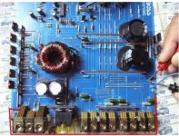
Have a good look at the bottom of the board. Take your time and use your glasses, or if you aren't like me, a magnifying glass.")
-Chris
What value did you come up with?i tested the resistance btw the pwr ground and the rca inputs' ground and both came up with a resistance.
A blown resistor would have been the best outcome.
Have a good look at the bottom of the board. Take your time and use your glasses, or if you aren't like me, a magnifying glass.
-Chris
tjmehta said:(not the cap being tested)
If u can see the numbers...it says C51..C=cap
thanks
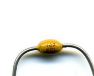
C normally indicates cap but I would be pretty certain your measuring a resistor. 47K(standard size) ohm likely or 370K(unlikely) ohm depending on which side you start on reading the bands. If you unsolder one lead you can make sure of the value. The 4.7K value would also explain your reading if your looking at the wrong scale.
If its a resistor C spot my guess is the board is made semi-universal or in some earlier design a cap was placed there. They could even use the same PCB on a couple amps to reduce production costs. Its hard to tell without looking in more detail at the pcb.
Those are most likely caps. Likely a ceramic cap. Resistors almost always have an endcap that makes the end more square. The attached image shows one without the color bands.
Caps used in that way are used to shunt high frequency noise from the heatsink to ground (assuming that the blue wire connects to the sink).
5 ohms is very low resistance from shield to chassis ground unless you had the RCA signal line plugged into the amp when you measured it.
Caps used in that way are used to shunt high frequency noise from the heatsink to ground (assuming that the blue wire connects to the sink).
5 ohms is very low resistance from shield to chassis ground unless you had the RCA signal line plugged into the amp when you measured it.
Attachments
Hi tjmehta,
So take the amp apart and have a good look. Your eyes are the best tool here (and experience). Again, some resistors can blow without showing any physical signs of damage.
You should make a point of checking your electronic crossover if you have one and the head unit for damage. Pay attention to the ground traces. You may get some odd faults with muting transistors too. DC offsets can be caused by those parts as well as just plain distortion.
-Chris
Yes, it is a bit low. One would normally expect anything from 10 to 100 ohms there. That's without anything else connected.5 ohms is very low resistance from shield to chassis ground unless you had the RCA signal line plugged into the amp when you measured it.
So take the amp apart and have a good look. Your eyes are the best tool here (and experience). Again, some resistors can blow without showing any physical signs of damage.
You should make a point of checking your electronic crossover if you have one and the head unit for damage. Pay attention to the ground traces. You may get some odd faults with muting transistors too. DC offsets can be caused by those parts as well as just plain distortion.
-Chris

Hi tjmehta,
4.67 K ohms would normally be far too high. Certainly higher than I would expect.
The TL494 is a PMW power supply controller IC. It drives the invertors and regulates the B+. If you "spark" it up, do you get any secondary voltages (on the outputs)? It's tough to kill those little guys but I have seen it done.
-Chris
what would cause that high resistance reading?
ive been looking over the board for everyday for two weeks plus..over and over..i dont see anything burnt anywhere.
if u dont think the 494 is messed up im going to leave that as a later option if u can think of anything else to check..
THANKS SO MUCH FOR HELPING ME TROUBLESHOOT
ive been looking over the board for everyday for two weeks plus..over and over..i dont see anything burnt anywhere.
if u dont think the 494 is messed up im going to leave that as a later option if u can think of anything else to check..
THANKS SO MUCH FOR HELPING ME TROUBLESHOOT
Retro,
These setups are basically a contest between the thermal capacity (to failure) of the fuse and the diode. I'll bet they really didn't test 100 or so to make sure the diode was beefy enough...
OR... the fault current didn't even pass through the fuse at all. Why Anatach is talking about fried copper instead.
- Status
- This old topic is closed. If you want to reopen this topic, contact a moderator using the "Report Post" button.
- Home
- General Interest
- Car Audio
- Blown amp (reversed polarity)