I am working on an older Lanzar Opti-Drive 100, 4 channel amplifier. The front two channels work well, but there is no sound and DC voltage (10-16v) across the rear speaker terminals. This amp uses TIP35C and TIP36C for the outputs, and I have replaced them all. There is + and - rail (26v) across the output transistors for the front channels, but across the rear there is only + and - 3 volts. Any help would be greatly appreciated.
Could you clarify a couple of things?
"DC voltage (10-16v) across the rear speaker terminals"
Does this mean that you have 10-16 volts from the right channel to the left channel or do you have 10-16 volts across each channel?
"There is + and - rail (26v) across the output transistors for the front channels, but across the rear there is only + and - 3 volts."
Does this mean that you have ±26 volts of rail on the front channels and only ±3 volts rail on the rear channels. It seems strange that you would have 10+ volts on the speaker outputs with only 3 volts of rail.
Please be as specific as possible including which terminals of the transistors you used for each measurement.
There is 16 volts DC on the rear speaker terminals, when testing with the meter positive probe on the speaker positive terminal, and the meter negative probe on the speaker negative terminal, for both the left and right rear channels.
Each channel has a TIP35C and a TIP36C. For the front channels (working channels) there is + and - rail (26v) on the TIP35Cs and the TIP36Cs. For the rear channels on the TIP35Cs there is + and - 38volts, and on the TIP36Cs there is + and - 3volts. Sorry I was unclear before, I appreciate the help.
Each channel has a TIP35C and a TIP36C. For the front channels (working channels) there is + and - rail (26v) on the TIP35Cs and the TIP36Cs. For the rear channels on the TIP35Cs there is + and - 38volts, and on the TIP36Cs there is + and - 3volts. Sorry I was unclear before, I appreciate the help.
DC coupling
I'm pretty sure that the OPAMPs in the preamp/crossover section are DC coupled to the amplifier. Soooo, if a dual OPAMP has been damaged in some way and is outputting its rail voltage straight into the two channels. Voila! You have that mysterious voltage at your terminals.
I'm not a psychic, but I've seen weirder things in Lanzar amps.")
I'm pretty sure that the OPAMPs in the preamp/crossover section are DC coupled to the amplifier. Soooo, if a dual OPAMP has been damaged in some way and is outputting its rail voltage straight into the two channels. Voila! You have that mysterious voltage at your terminals.
I'm not a psychic, but I've seen weirder things in Lanzar amps.
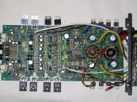
Can you post a good quality photo of the amp?
Are you sure that you have the replacement transistors (35/36) in the right place?
Are the symptoms now, precisely the same as before you replaced the transistors?
Have you checked the regulated voltage for the rear channels (±15 on the op-amps)?
On the front channels, is the rail voltage on the center terminals of the outputs or on the right-most terminals?
They are in the right place and there is 15 volts on all of the op amps. I am new at this so I will try to explain in detail where I am getting the numbers from. I also attached a picture.
With the meter negative probe on the secondary center tap, and the meter positive probe on the center leg of the TIP35Cs, it reads + 26 volts for all four (front and rear)
With the meter negative probe on the secondary center tap, and the meter positive probe on the center leg of the TIP36Cs, it reads - 26 volts for all four (front and rear)
With the meter negative probe on the secondary center tap, and the meter positive probe on the left leg of the TIP35Cs, it reads:
front = 0.2 volts rear = 16 volts
This same measurement for the right leg reads the same.
With the meter negative probe on the secondary center tap, and the meter positive probe on the left leg of the TIP36Cs, it reads:
front = 0.1 volts rear = 16 volts.
This same measurement for the right leg reads the same.
With the meter negative on the left leg of the TIP35Cs, and the meter positve on the center leg, it reads:
front= 0.3 volts rear = 38 volts
With the meter negative on the left leg of the TIP35Cs, and the meter positve on the center leg, it reads:
front= 0.3 volts rear = 3 volts
There's something wrong with the readings. For the following values:
"With the meter negative on the left leg of the TIP35Cs, and the meter positve on the center leg, it reads:
front= 0.3 volts rear = 38 volts"
The good channel should show 26 volts difference. The center leg is the rail (26v) and the first leg is the base. The base should be within 0.7 volts of the speaker output voltage which is essentially at ground.
Re-measure the values and drop them into this format:
TIP35C left rear
Pin 1:
Pin 2:
Pin 3:
TIP36C left rear
Pin 1:
Pin 2:
Pin 3:
TIP35C right rear
Pin 1:
Pin 2:
Pin 3:
TIP36C right rear
Pin 1:
Pin 2:
Pin 3:
TIP35C one front channel
Pin 1:
Pin 2:
Pin 3:
TIP36C one front channel
Pin 1:
Pin 2:
Pin 3:
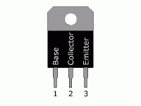
The pin numbering is left to right with the tab above the leads and the transistor facing you (able to read the part number). Use the center tap of the secondary as the reference for all of the readings. Be particularly accurate with pins 1 and 3. The difference between them may only be 1/2 volt. The amp should be on with no signal.
When you post an image, you have to preview the post (if desired) 'then' attach the photo. If the post is long and detailed, I'd recommend that you copy it to another editor before attaching the image. I've had a few instances where the image was too large and I could not return to the text.
You said you had 15 volts on the op-amps, did you have BOTH plus and minus 15v?
"With the meter negative on the left leg of the TIP35Cs, and the meter positve on the center leg, it reads:
front= 0.3 volts rear = 38 volts"
The good channel should show 26 volts difference. The center leg is the rail (26v) and the first leg is the base. The base should be within 0.7 volts of the speaker output voltage which is essentially at ground.
Re-measure the values and drop them into this format:
TIP35C left rear
Pin 1:
Pin 2:
Pin 3:
TIP36C left rear
Pin 1:
Pin 2:
Pin 3:
TIP35C right rear
Pin 1:
Pin 2:
Pin 3:
TIP36C right rear
Pin 1:
Pin 2:
Pin 3:
TIP35C one front channel
Pin 1:
Pin 2:
Pin 3:
TIP36C one front channel
Pin 1:
Pin 2:
Pin 3:
The pin numbering is left to right with the tab above the leads and the transistor facing you (able to read the part number). Use the center tap of the secondary as the reference for all of the readings. Be particularly accurate with pins 1 and 3. The difference between them may only be 1/2 volt. The amp should be on with no signal.
When you post an image, you have to preview the post (if desired) 'then' attach the photo. If the post is long and detailed, I'd recommend that you copy it to another editor before attaching the image. I've had a few instances where the image was too large and I could not return to the text.
You said you had 15 volts on the op-amps, did you have BOTH plus and minus 15v?
TIP35C left rear
Pin 1: -16.8
Pin 2: +26
Pin 3: -16.3
TIP36C left rear
Pin 1: -16.6
Pin 2: -26
Pin 3: -17.3
TIP35C right rear
Pin 1: -16.8
Pin 2: +26
Pin 3: -16.3
TIP36C right rear
Pin 1: -17.3
Pin 2: -26
Pin 3: -16.5
TIP35C one front channel
Pin 1: +0.7
Pin 2: +26
Pin 3: +0.2
TIP36C one front channel
Pin 1: +0.1
Pin 2: -26
Pin 3: +0.2
I am getting + and - 16.5 to 17 volts on all four of the op amps. I attached a picture, but I had to decrease the resolution quite a bit to get it to upload.
Pin 1: -16.8
Pin 2: +26
Pin 3: -16.3
TIP36C left rear
Pin 1: -16.6
Pin 2: -26
Pin 3: -17.3
TIP35C right rear
Pin 1: -16.8
Pin 2: +26
Pin 3: -16.3
TIP36C right rear
Pin 1: -17.3
Pin 2: -26
Pin 3: -16.5
TIP35C one front channel
Pin 1: +0.7
Pin 2: +26
Pin 3: +0.2
TIP36C one front channel
Pin 1: +0.1
Pin 2: -26
Pin 3: +0.2
I am getting + and - 16.5 to 17 volts on all four of the op amps. I attached a picture, but I had to decrease the resolution quite a bit to get it to upload.
Attachments
Did you use the pin numbering as shown in the attached image.
Pin 3 of each channels transistors should be virtually identical. For example, the left channel has 1 full volt across the emitter resistors. If this is the case, the amp should be drawing significant current (10+ amps) and the output transistors should be getting hot. Open or out-of-tolerance emitter resistors could explain why it would not be drawing current but if they were defective I'd expect to see the third terminal of the TIP35 above ground potential.
Pin 3 of each channels transistors should be virtually identical. For example, the left channel has 1 full volt across the emitter resistors. If this is the case, the amp should be drawing significant current (10+ amps) and the output transistors should be getting hot. Open or out-of-tolerance emitter resistors could explain why it would not be drawing current but if they were defective I'd expect to see the third terminal of the TIP35 above ground potential.
Attachments
Ok, I remeasured and this is what I got. The numbers fluctuate by roughly 0.3 volts on some of them, I took the average.
TIP35C left rear
Pin 1: -16.9
Pin 2: +26
Pin 3: -16.3
TIP36C left rear
Pin 1: -16.5
Pin 2: -26
Pin 3: -16.3
TIP35C right rear
Pin 1: -16.8
Pin 2: +26
Pin 3: -16.3
TIP36C right rear
Pin 1: -17.1
Pin 2: -26
Pin 3: -16.4
TIP35C one front channel
Pin 1: +0.7
Pin 2: +26
Pin 3: +0.2
TIP36C one front channel
Pin 1: +0.1
Pin 2: -26
Pin 3: +0.2
The right rear seems like it's being driven 'on' which could explain the offset. The other channel is within the margin of error you stated so it's possible that it is also being driven to -16 volts.
Since you have a set of good channels, you can compare those to the defective channels. It's possible that there is a broken ground or power supply connection. I'd suggest comparing the voltages on one driver board to the other.
If you have a scope or other means of tracing the signal, drive one channel at a time to determine which pins on the driver boards are the signal pins. If you have 4 good signals going into the driver boards, you know that the problem is on or beyond the driver board.If you have negative voltage on the signal input pins of the driver board, then the problem is before the driver board.
Unless there is a broken power supply connection to the positive drivers, it's unlikely that the problem is beyond the driver board because both channels have the same problem.
- Status
- This old topic is closed. If you want to reopen this topic, contact a moderator using the "Report Post" button.
- Home
- General Interest
- Car Audio
- DC on the speaker outputs, Lanzar Opti 100