Second-hand textronix 465 could be a good deal, but I have no idea where to buy 2-hand scopes in ThailandClipped said:
ive been meaning to get a scope, but just kinda afraid it wont see enough use to make it feasible....any recommendations for a good cheap one?
thanx
")
Brand new Instek GDS-820C digital scope is around 1000 euro, looks usable on specs.
With the amp on, measure the DC voltage on all pins of the muting transistors. The black meter lead will be grounded to the RCA shield ground. Post your results.
When you reinstalled the transistors, did you reinstall them with proper orientation? Generally, pin 1 of the transistor goes to the square pad. On all of the orions amps of that model that I've seen, the muting transistors are installed backwards from this. This is only true of the jfets. I believe all 3 jfets are installed this way but I know the 2 muting jfets are installed this way (I'm not sure of the one near the power supply).
Tektronix makes great scopes. The 400 series scopes are rugged and can be repaired relatively easily because most of the parts are generic and still available. Don't buy a 2400 series scope. They have hybrid modules that fail and are no longer available as a new part.
Although it's nice to have a 100 meg scope (like the 465 -- the 465 and 465B scopes are very good), it's not necessary for audio work. I used one of the 5000 series Tek scopes (only a 2 meg scope) for several months and it did everything that I needed to do. If you can find a 10, 20, 50 meg scope in good working order, it will work well for troubleshooting audio and power supply problems.
Hi all,
Leader or Iwatsu, as additional possibilites. We use several Leader units in our labs, as they are fairly inexpensive - most of the problems are associated with contact corrosion.
I tend not to like the sound-card solutions because they won't show DC.
my 2c
Cheers!
Clem
Leader or Iwatsu, as additional possibilites. We use several Leader units in our labs, as they are fairly inexpensive - most of the problems are associated with contact corrosion.
I tend not to like the sound-card solutions because they won't show DC.
my 2c
Cheers!
Clem
Hi Clem,
I agree with your statements.
Making a correct attenuator for your sound card input is not easy. You need a scope or accurate meter with good HF response. I'd suggest an HP 34401a (-3dB @ 300KHz) or equiv. for this.
Just buy a 'scope. The sound card thing has other uses.
Anyone check out the new Agilent 3000 series. I am going to test one, it's a DSO with FFT math built in. Less than $2000 CDN. Don't ask me how much my Philips PM3070 cost.
-Chris
anatech said:Anyone check out the new Agilent 3000 series. I am going to test one, it's a DSO with FFT math built in. Less than $2000 CDN. Don't ask me how much my Philips PM3070 cost.
Hi Chris,
Ouch!!
Lower-cost option: get the lowest-end Tek, add the computer comms module. Do the FFT on the computer (that is, if FFTs are only to be used occassionally).
Admittedly, the sound card will have better amplitude resolution, owing to the 16bit AD. Sampling rate is limited though, save for the more expensive ones - if you work only in the audio band...
Cheers!
Clem
Hi Clem,
If I can get away cheaper and still have a great reliable product then I will.
Sound cards will generally not show harmonics over 20KHz that I've seen. Attenuator is a pain. My current 'scope cost over twice that of the Agilent, but I'm hurting for money so I only want to spend it once. The Philips has failed a few times now. Expensive POS.
Since I need a 'scope and I would love usable FFT, I hope to combine the functions.
-Chris
Hi Chris,
Some of the new sound cards boast 192KHz sampling with 24-bit ADCs. A proper FFT should be able to show harmonics a fair bit beyond 20KHz, assuming the manufacturer didn't put in a non-programmable anti-alias. I have to admit though I've never tried them new-fangled cards...
Cheers,
Clem
Some of the new sound cards boast 192KHz sampling with 24-bit ADCs. A proper FFT should be able to show harmonics a fair bit beyond 20KHz, assuming the manufacturer didn't put in a non-programmable anti-alias. I have to admit though I've never tried them new-fangled cards...
Cheers,
Clem
Perry Babin said:With the amp on, measure the DC voltage on all pins of the muting transistors. The black meter lead will be grounded to the RCA shield ground. Post your results.
When you reinstalled the transistors, did you reinstall them with proper orientation? Generally, pin 1 of the transistor goes to the square pad. On all of the orions amps of that model that I've seen, the muting transistors are installed backwards from this. This is only true of the jfets. I believe all 3 jfets are installed this way but I know the 2 muting jfets are installed this way (I'm not sure of the one near the power supply).
ive been running the amp with the muting transistors out (2 of them) hope it doesnt do it any harm...
i have to put the muting transistors back in before i check them again...but i need to clear something up first...
if im holding the jfet with my fingers with the 'rounded part facing' me... is pin '1' the one on the left?...or am i holding it backwards?....not quite sure which side the front of the jfet is...
at the moment all 3 jfets have the same pin in the square pad
oh and btw:
amp 1's power supply is also making a 'squelching' sound, but amp 2's doesnt...but i think i should go one step at a time...

muchos gracias
my heads spinning after reading all the scope info, need some time to digest it all
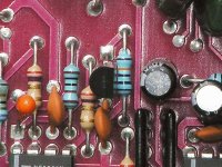
Almost without exception, if you're looking at the side of the transistor with the text/markings, pin 1 is on the left. This means that you would have the larger, flat surface facing you.
I've attached an image that shows the muting transistors as they are installed from the factory.
I've attached an image that shows the muting transistors as they are installed from the factory.
Attachments
yep thats how its mounted right now from the factory...so i have to take them out and reverse them ehhh?
goodlord... the source of my frustration was a factory defect in manufacturing?
the 3 rd jfet by the power supply is also mounted the same way.
should i reverse them all? or should i give you a reading first?
havent had time to mount them yet...ive literally built 7 boxes this week and my lungs are full of mdf...
thanx
Clipped:
The transistors have to be installed as in the photo. If yours were/are the other way, reverse them. If you have some new ones, use them instead of the ones that were installed backwards. They should be OK but there's no point in using them if you have new/unused components.
I have images of more than 100 amplifiers. More than 1000 images in total. They are part of the tutorial.
AndrewT:
I use an Olympus C740 with a set of cheap close-up lenses and a tripod.
Perry said:
Almost without exception, if you're looking at the side of the transistor with the text/markings, pin 1 is on the left. This means that you would have the larger, flat surface facing you.
When you reinstalled the transistors, did you reinstall them with proper orientation? Generally, pin 1 of the transistor goes to the square pad. On all of the orions amps of that model that I've seen, the muting transistors are installed backwards from this. This is only true of the jfets. I believe all 3 jfets are installed this way but I know the 2 muting jfets are installed this way (I'm not sure of the one near the power supply).
The transistors have to be installed as in the photo. If yours were/are the other way, reverse them. If you have some new ones, use them instead of the ones that were installed backwards. They should be OK but there's no point in using them if you have new/unused components.
ok im a little confused
if pin one is on the left, then isnt the jfet in the picture mounted incorrectly?
in the picture, pin 3 is in the square pad
help...

but anyway , i put them back in, like in the picture...and here are the readings:
with rca's pointing away from me
left jfet
left pin 0.000
middle pin 0.000
right pin -0.001
right jfet
left pin 0.000
middle pin 0.000
right pin -0.001
power supply jfet
left pin -0.047
middle pin 0.000
right pin -22.47
all jfets have pin 3[right pin] in the square pad...this is if the flat surface is facing me...after putting them back in the sound dissappeared again
The jfets are not installed normally in these amplifiers. I don't know if they made a mistake when laying out the board or if they found FETs that performed better but had a reversed pin configuration.
The jfet near the supply should have negative voltage on pin 1 also. The Jfets are normally 'on'. This shunts the audio to ground and mutes the amp when there in no voltage between the gate and source. To turn the jfets off, you need to drive the gate with a negative voltage. For these jfets, the gate voltage has to be approximately negative 8 volts to switch them off.
Check the 220k ohm resistor and the diode that's connected to it. They are both near the power supply jfet. Pull 1 leg of the resistor to check it. Check the diode on both resistance and diode check while the resistor is desoldered. Remember to check the diode in both directions. If there is any indication that the diode is leaking, replace it. If it's open, of course, it needs to be replaced.
The diode and resistor charge the electrolytic cap (near the P/S jfet) to ~ negative 24 volts. When the muting circuit is to be disengaged, the optocoupler sends voltage to the 2 audio jfets and they no longer clamp the audio signal to ground.
- Status
- This old topic is closed. If you want to reopen this topic, contact a moderator using the "Report Post" button.
- Home
- General Interest
- Car Audio
- How do you check opamps?