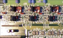
I'm working on this amplifier and need to find info on some semiconductors that zapco used in this thing. They are to92 type and they are on the front end of the amp. I can take some pics if need be. The part numbers on the transistors and locations on the board are; Q41-c436aj, Q48-c436aj, Q49-c448ab, Q54-c436aj, Q55-c448ab, Q60-c436aj, Q65-c448ab, Q72-c448ab. I've tried to cross them and find data sheets with no luck. With them out of circuit, two of the three legs show about 4ohms in either direction on both types and on the exact two legs. The middle leg to the third leg shows high resistance. I'm stuck. Don't know if they are regulators or some kind of mosfets or just bad transistors. The four 100uf caps in the same section did leak their electrolytic fluid. All the surface mount transistors in the area do not show any shorts. Would like to know what could work in there place. Any help would be greatly appreciated.
Scott

Scott
Try adding 2S in front of all the part numbers:
http://www.google.co.uk/search?hl=en&q=2sc436&btnG=Google+Search&meta=
http://www.google.co.uk/search?hl=en&q=2sc436&btnG=Google+Search&meta=
From the meter readings, it sounds like they're some sort of jfet but I've never seen a jfet with 4 ohms of on resistance. ~20 ohms is the lowest I've seen.
It's virtually impossible to have 8 transistors fail and give precisely the same readings.
What sort of problems were you having with the amp?
Were all 4 channels out?
It's virtually impossible to have 8 transistors fail and give precisely the same readings.
What sort of problems were you having with the amp?
Were all 4 channels out?
I benched it and it does power up about half the time. When it does power up, idle current is a little over 2 amps, preaty normal. When it doesn't power up correctly, it flashes the clip and fault LEDs on a 1 or 2 second cycle and stays that way until turn on power is removed. Nothing is burned on the PCB. I've replace all the finals and the power supply mosfets. Zapco told me-"Usually Zapco has bad electrolytics, value about 100uF is the usual suspect. Change all these small caps; if you have time, they are up to their time. Usually the "bad" residue is not white, but brown. And it is semi liquidous. Usually you cannot see them until you remove the SMD component first. They are corrosive to the copper PCB tracks. After you clean the suspected sections, spray all the pcb with contact cleaner, and brush them with used tooth-brush. This way will clean all."
I still wish I could find out what those eight transistors are
I still wish I could find out what those eight transistors are
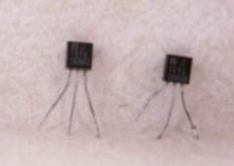
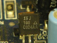
I found a similar component in the Xtant I'm working on and found similar readings that confirmed that they are jfets. I attached a photo of the one I have. The part number is J108. Here is its datasheet:
http://www.vishay.com/docs/70231/70231.pdf
I was suprised to see that they have jfets with Rds-on of 3 ohms.
I believe that your components are good and you can look elsewhere for the problem.
When you have leaky capacitors, the residue of corroded copper and electrolyte is conductive. If the area under the capacitor doesn't come completely clean, make sure that you scrape the area between the capacitor's pads to break any conductive path.
If you have to remove any surface mount resistors or small surface mount capacitors, you need to use silver-bearing solder when replacing them. This goes for any surface mount component that has ceramic base material.
Attachments
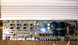
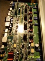
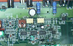
Yes sir, the pic you posted has the same manufacture stamp as the trans in question. This zapco is a 4 layer board which makes it more fun to deal with. I did a quick check on the SMD's (caps, res, transistors) around the leaky caps and did not find any shorts but I know that the caps leaked and I have to clean it up. I just hope that it didn't ruin the layers beneath. I can't believe that zapco made such a bo bo with caps in such an expensive product. I show that it listed for $1499 back in 1998. The date stamp on the board is 1994. If I get really stuck on this, I might send it to justrepairs.com or somebody that can repair this particular model and pay the money. I really appreciate the info on the transistors. I'll keep chugging away and scratching my head.
Thanks
Scott
Thanks
Scott
Any equipment with four layer boards is a pain to repair. For small signal and digital circuits it may be OK, but in power applications traces and plated thru-holes in the inner layers tend blow without you having any chance to notice.
Also, with the usual single or double sided PCBs you have a chance to draw your own schematic and trace any fault, but with four layer boards you just can't do that, so a schematic from the manufacturer is required.
Concerning Zapco, don't get fooled, extreme complexity, high prices and a lot of hype doesn't necessarily mean reliability at all. You may actually find some low-cost Chinese amplifiers to be more reliable than those ultra-complex high-priced models.
Your right, they were not very helpful and they will not give up a schematic. I've had luck with soundstream emailing schematics to me for the old reference and rubicon amplifiers. I have them for the ref 1000s and the rub 1002 if someone needs one I can email the pdf file to them. Some of the old orion amps (sx series) switching power supply semiconductors made buy GE are getting tough to find. The zapco looks like it was never abused. All the traces are clean and not bubbled. Just by looking at it with the naked eye, you would never see that the caps leaked. I give it my best shot to fix it.
Scott
Scott

Siliconix/Vishay.
This site has logos for many of the electronic component manufacturers. It may be helpful in the future.
http://info.electronicwerkstatt.de/bereiche/bauteile/ic_logo/
This site has logos for many of the electronic component manufacturers. It may be helpful in the future.
http://info.electronicwerkstatt.de/bereiche/bauteile/ic_logo/
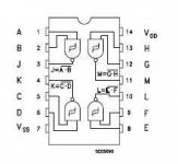
siliconix part number j109
The jfets in this zapco have the siliconix part number j109 next to their symbol. This amp has eight of them but 4 have a number C448AB and the other 4 have C436AJ. The data sheet for j109 covers all eight as being the same. What would these other numbers indicate? Are they some kind of S/N or manufacture sequence. Basically, would it be safe to replace all eight of these with the j109? Just wondering...
The jfets in this zapco have the siliconix part number j109 next to their symbol. This amp has eight of them but 4 have a number C448AB and the other 4 have C436AJ. The data sheet for j109 covers all eight as being the same. What would these other numbers indicate? Are they some kind of S/N or manufacture sequence. Basically, would it be safe to replace all eight of these with the j109? Just wondering...
Yes the J109’s are just JFET’s and that’s that. I did finally fix this amp and posting to share and maybe help someone else. The caps did leak and replacing them is all that I did. THEY DID NOT DAMAGE the board. I found a timing issue with a HCF4093 QUAD 2 INPUT NAND SCHMITT TRIGGER located at U20. The 10uf 50v cap connected to pins 12 and 13 was making the amp not start all the time. I found this when I removed the cap and the amp started every time. I opted to put a 100uf 50v cap in its place and everything works fine. So after replacing all the out-put finals, power supply MOSFET’s, full wave bridge, all 12 op-amps and many caps, it turned out to be just the four leaking caps in the preamp stage and the timing issue. It sucked working on a four layer board without a schematic!, THANKS ZAPCO FOR ALL YOUR HELP! (NOT). Just thought I would share.
Thanks every-one for all the help and advice.
Scott

Thanks every-one for all the help and advice.
Scott
Attachments
- Status
- This old topic is closed. If you want to reopen this topic, contact a moderator using the "Report Post" button.
- Home
- General Interest
- Car Audio
- Zapco Z400C4-SL