This is an a/d/s/ 640 amp, I have replaced 1 pair of output transistors, all of the output resistors. 3 of 8 power fets were gone, replaced all of those...
Now it looks as if I keep blowing little resistors in one of the feedback sections of the channels that was toast.... the original repairer replaced a motorola chip with a toshiba, 1/2 watt resistor instead of 2 watt, used 5% resistors where 1% were formerly, and now that channel is giving me burnt up resistors when I give it power. I'm thinking there is a small transistor gone or something since it's just 1 channel that's popping resistors...
This is where I'm at, I just replaced the brown black black black brown resistor, and it fried again...
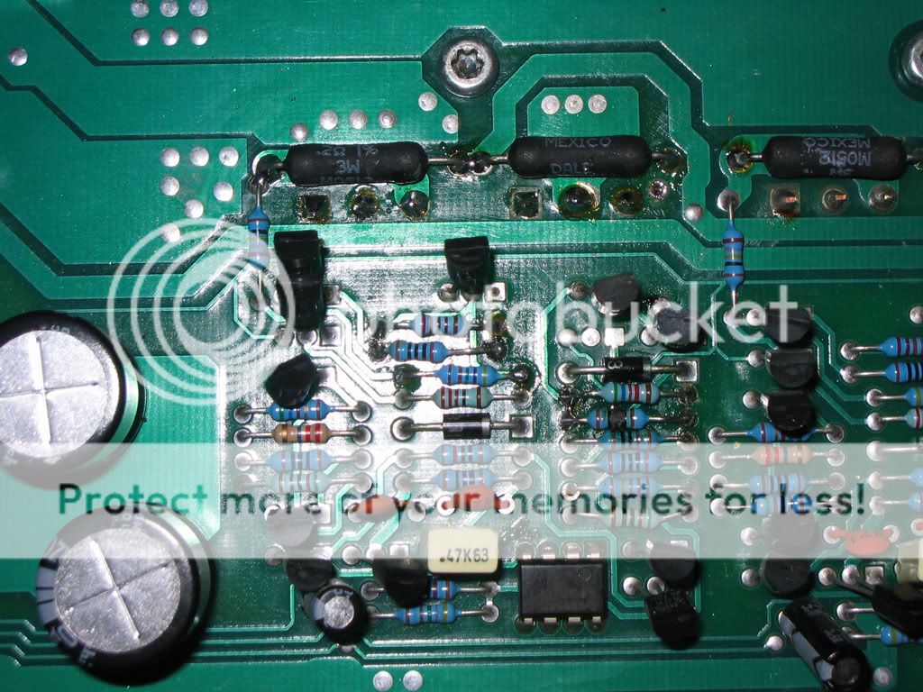
this is where I was before:
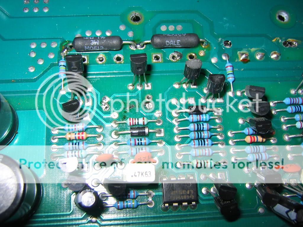
it had fried some other resistors before it, and now just taking out one at a time... I was fine with a 80hz tone and current limiting resistor, but I wasn't getting any output, I was afraid to throw the sound through my speakers because I have yet to get a dc protection cap on them :-/ but didn't seem like it was capable of driving even the dummy load resistors, jsut started to crackle...
It looks like the TL494 PWM chip is chirping away, but I may have possibly fried some more power fets? current draw would jump up/down for a while, then settle down. It seemed fine, but may have blown out the power fets again...
So my question, if I replaced all the resistors correctly, and these are blowing, is it possible one of these 20 or so little transistors are blown? Or what about this TI LF351P dual JFET Opamp? there's a little dirt near that... can I test that like a BJT? It's also the only one that's not shiny... but I may have gotten my grimy fingers on it... here's that spec sheet:
http://focus.ti.com/general/docs/lit/getliterature.tsp?genericPartNumber=lf351
here's a big pic of the amp:
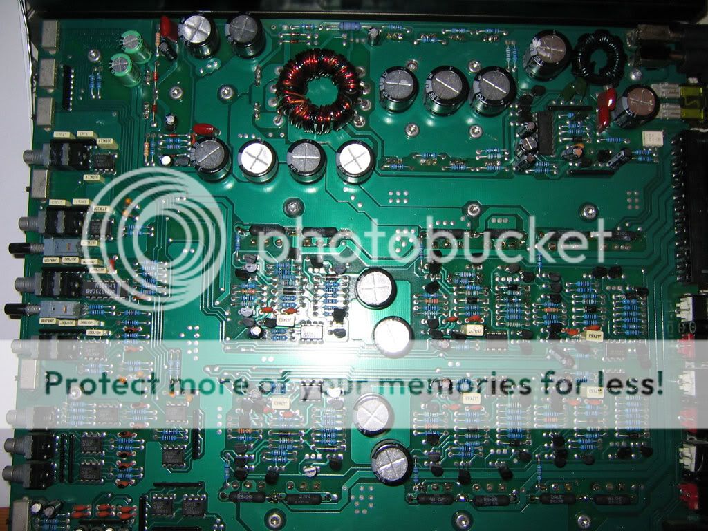
Much larger format 2048x1000 or so image:
http://img.photobucket.com/albums/v511/Ocelaris/Amps/ads640/IMG_0010smaller_file.jpg
Thanks for the help!
Now it looks as if I keep blowing little resistors in one of the feedback sections of the channels that was toast.... the original repairer replaced a motorola chip with a toshiba, 1/2 watt resistor instead of 2 watt, used 5% resistors where 1% were formerly, and now that channel is giving me burnt up resistors when I give it power. I'm thinking there is a small transistor gone or something since it's just 1 channel that's popping resistors...
This is where I'm at, I just replaced the brown black black black brown resistor, and it fried again...
this is where I was before:
it had fried some other resistors before it, and now just taking out one at a time... I was fine with a 80hz tone and current limiting resistor, but I wasn't getting any output, I was afraid to throw the sound through my speakers because I have yet to get a dc protection cap on them :-/ but didn't seem like it was capable of driving even the dummy load resistors, jsut started to crackle...
It looks like the TL494 PWM chip is chirping away, but I may have possibly fried some more power fets? current draw would jump up/down for a while, then settle down. It seemed fine, but may have blown out the power fets again...
So my question, if I replaced all the resistors correctly, and these are blowing, is it possible one of these 20 or so little transistors are blown? Or what about this TI LF351P dual JFET Opamp? there's a little dirt near that... can I test that like a BJT? It's also the only one that's not shiny... but I may have gotten my grimy fingers on it... here's that spec sheet:
http://focus.ti.com/general/docs/lit/getliterature.tsp?genericPartNumber=lf351
here's a big pic of the amp:
Much larger format 2048x1000 or so image:
http://img.photobucket.com/albums/v511/Ocelaris/Amps/ads640/IMG_0010smaller_file.jpg
Thanks for the help!
It's not likely that the op-amp is causing the resistors to burn.
If one of the transistors is leaking or shorted, it could cause the resistors to burn.
If you can't find any damaged transistors, try to get a schematic from ADS.
I noticed that one transistor looked badly bent in one of the photos. If it's bent badly enough to short the leads, that could be causing you problems.
Not sure if the first pic was clear...
It looks like for Mosfets I must remove them from the board to test them, at least that has been my experience so far.
But the MJL3281 and MJL1302 BJTs (I believe they are BJTs) and other transistors I can test in board. Is this correct? That would simplify alot, but is there a hard and fast rule as to what type of components you can test in board and which ones you can not?
Thanks as always
If a transistor is shorted, that's easy to find with the transistor in the circuit. If there is a question as to whether the transistors are leaking or open, it's generally best to remove the transistors to test them. When learning to do this type of work, I'd recommend pulling the transistors.
Did you try to find a schematic?
Did you try to find a schematic?
Trying to understand why some resistor blows in such a non-trivial circuit without an schematic (either in paper, in computer screen or in mind) is just *not* possible. You are required to understand how the circuit works first in order to fix such a failure.
If you can't get a schematic, strart drawing one right now. It will be time consuming, but it will take much more time to find out the problem going blind without a schematic.
If you can't get a schematic, strart drawing one right now. It will be time consuming, but it will take much more time to find out the problem going blind without a schematic.
I haven't had time to disasseble the board again, but found 2 things of concern...
The little to-92 transistors were replaced with NTE 159 and 287 PNP and NPN instead of the Motorola A06 and A56 transistors... Only 4 of maybe 12 in this circuit were replaced with NTE equivalents, this is the same channel that had a Toshiba chip instead of the Motorola equivalent... Part of the reason the to-92 transistors were so bent was because they were put in after the fact, and it was a sloppy job... I probably didn' t help, but these were soldered in place at a 63* angle it seems
Also upon further inspection, managed to short a output transistor to the heatsink...
So basically need to take every chip off and test, then see where I am at that point. Order some replacements if necessary. If it wasn't obvious, this is my first repair, and I'm making mistakes left and right, but getting better at desoldering and removing chips!
Do they make a tool to hold the board for you while you work on both sides? Seems like a good idea, hard to suck and solder at the same time on opposing sides... my chin is getting plenty of work!
Thanks again for all the help
In the future, I'd recommend against the NTE components. They are fine in most cases but I've seen quite a few that simply didn't work as they should (especially in switching power supplies). The originals are cheaper and are more likely to work properly.
When desoldering components, the iron and the desoldering pump are on the same side of the board. For small transistors with all 3 legs in a row, you can add new solder to the connections. Then lay your iron tip across all 3 terminals and pull the transistor. After the new solder is added to the board, the whole process should take less than 5 seconds. If the legs of the transistor are bent over (to hold them in place while the board is being assembled). you need to straighten them before trying to pull the transistor. When adding new solder, place the tip of the iron on the tip of the transistor's legs and lift it until it's perpendicular to the board. Don't apply pressure to the copper on the board. Only apply pressure to the wire lead of the transistor. After the transistor is removed, desoldering is easier.
Generally, the only time it's necessary for the iron and desoldering pump to be on opposite sides of the board is when there is heavy copper (acting as a heatsink) and there's insufficient space to get both the iron and desoldering tool on the solder pad at the same time.
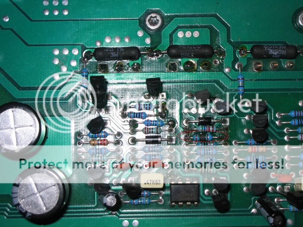
Couldn't sleep, did some work, think I found the problem...
Some of the to-92 transistors that the previous repair person replaced are faulty. I found out I could test those in board which is nice. I would test 1 in board, then out of board, and compare the results.
I tested these by putting my test lead on the base (center pin) and the other test lead on the other pin, and reading the results... if it was PNP I would use black lead center, positive on either leg, NPN reversed. Was coming up with I think around .6v drop... all the original ones were fine. I used your Green tester diagram Perry to figure that one out...
Pulled all the fets, they were all fine, within .1v drop of each other (whew)... and pulled what appeared to be a shorted output transistor... which tested fine. Also I could test those inboard. Those were BJTs.
The to-92 transistors had burned some of the PCB around them like where the small 1/4watt resistors were burning up also, so this makes me hopeful this is all the problem was... also the turn on LED was burned out, replaced that little 3mm guy.
Feeling much better now about the whole project... just wanted to share
I didn't replace them with NTE parts, this amp had been repaired before and they used sub par parts all around, and I've been finding these parts, discovering that they have failed, slowly... this was the smallest I could find, and hopefully the last, as this is really the only channel that is bad to my knowledge...
I am building my parts collection, I am trying to use all oem parts if possible. I ordered them from Mouser thursday night, so should be here soon to find out.
Thanks for the help all, I really appreciate the help!
I am building my parts collection, I am trying to use all oem parts if possible. I ordered them from Mouser thursday night, so should be here soon to find out.
Thanks for the help all, I really appreciate the help!
what causes negative rail voltage on speaker outputs?
Ok, Got the amp in much better shape I believe. Replaced a bunch of blown to-92 transistors, and now we're in good shape but I'm not out of the woods yet... It's not pulling any exorbitant amounts of current at idle, with our without current limiting power. So that is good... when I give it a load it pulls alot of power though...
I'm getting a full negative rail voltage on that channel on the channel two speaker lead... and I checked the large output Transistor and it compares favorably compared to known good channels, ~.522v drop across on them...
There are no paralell output transistors on any channel, it's just 1 large BJT to-247...
what should I check, power supply? I just replaced the rectifiers, even though they tested fine...
Sorry if this is a stupud question, but I've been working on this amp the past 6 hours off and on and my brain is fried... everytime I'm about to post, I go check something, and make another step... have done this 4 times now, but now I'm beat... any ideas?
Have you tryed to get schematics from ADS? Sometimes they will let them go. Also This might help...
http://ampguts.realmofexcursion.com/
Pretty good pics that might help.

http://ampguts.realmofexcursion.com/
Pretty good pics that might help.
Re: what causes negative rail voltage on speaker outputs?
Take a few days off, and come back to it later. Sometimes it takes the mind a while to think through a problem, even if it does it unconsciously, and sometimes approaching even the most difficult problem after a while away helps a lot.
Ocelaris said:Sorry if this is a stupud question, but I've been working on this amp the past 6 hours off and on and my brain is fried... everytime I'm about to post, I go check something, and make another step... have done this 4 times now, but now I'm beat... any ideas?
Take a few days off, and come back to it later. Sometimes it takes the mind a while to think through a problem, even if it does it unconsciously, and sometimes approaching even the most difficult problem after a while away helps a lot.
- Status
- This old topic is closed. If you want to reopen this topic, contact a moderator using the "Report Post" button.
- Home
- General Interest
- Car Audio
- Help? blowing little Resistors in Feeback Section