Hello Everyone,
I have an Soundstream Reference 405, The sub channel keeps blowing woofers, literally it smokes them
I measured the output comming from the speaker terminals and it measured 30 volts.
I opened the soundstream 405 540-621 rev 6 amp this weekend looking for signs of burned components but found non, I then removed the silver screws out and fliped the board to check for burned transistors they all appeared clean no "physically" burned components I could find.
I called soundstream and they promptly emailed me the schematic diagram for both the sub-channel and power supply.
Could someone please post me instructions on how to properly check if the transistors are good using a multimeter? I was planning on replacing all the transistors at the power supply side to start but thought maybe someone here can point me to the right direction to take. Thanl you!
--Roberto
p.s: soundstream wanted $125 just to look at it.
There's an excellent web page for newbies like yourself , http://www.bcae1.com/ on the side panel goto number 97 "output transistor faliure". It shows you how to check them. IF your getting that much dc on the output then you have a bad transistors.
swordfish689, thanks for the info I'm reading that page now and will try to diagnose tonight.
I think it's best to replace all SIX TIP102 transistors which are Q607, Q608, Q609, Q610, Q611, Q612 as well as all SIX TIP107 transistors which are Q613, Q614, Q615, Q616, Q617, Q618 as seen in this schematic I'm attaching.
I'm also planning on replacing the following FED16BT components D103, D104, D105, as D106 depending on what I find when I do my diagnostics tonight.
I'll also do a resistance check on all the resistors near the output section especially
the lower ohm values.
I think this amp is worth the effort and cost to fix. I like the clean sound it produces and the one amp solution setup it provides.
--Roberto
Thanks again swordfish689,
I checked for gate leakage or short using the website you graciously provided
http://www.bcae1.com/
and here's what I found out. Just to be safe I used a fluke 81438 and my old trusted fluke 73 multimeter.
All the motorolla TIP120 519 have gate leakage or short no matter which fluke I use
All the motorolla TIP107 520 also have NO gate leakage on G + D but have leakage on G+S so they still fail.
Ordered all the TIP102 and TIP107 from digikey last night part #: 497-2546-ND, 497-2606-ND respectively,
I also tried checking all the caps on the ultra-low esr capacitor bank (1000UF 16 volts) and they don't seem to charge up.
they are yellow right side below the coil. I will have to replace all of them as well.
There's also gate leakage or short with these
GIFED16BT
FA277FEP16BTD
GIFED16BT 9508
Motorolla mc T7815CT
Korea 436 KA7915
TP50N0SE 527
I'm not sure if these are NPN Darlington power transistors I will try and ask soundstream today for more information, Can someone please inform me what kind of transistors these are?
Aghain thanks for the information.
--Roberto
I checked for gate leakage or short using the website you graciously provided
http://www.bcae1.com/
and here's what I found out. Just to be safe I used a fluke 81438 and my old trusted fluke 73 multimeter.
All the motorolla TIP120 519 have gate leakage or short no matter which fluke I use
An externally hosted image should be here but it was not working when we last tested it.
All the motorolla TIP107 520 also have NO gate leakage on G + D but have leakage on G+S so they still fail.
An externally hosted image should be here but it was not working when we last tested it.
Ordered all the TIP102 and TIP107 from digikey last night part #: 497-2546-ND, 497-2606-ND respectively,
I also tried checking all the caps on the ultra-low esr capacitor bank (1000UF 16 volts) and they don't seem to charge up.
An externally hosted image should be here but it was not working when we last tested it.
they are yellow right side below the coil. I will have to replace all of them as well.
There's also gate leakage or short with these
GIFED16BT
FA277FEP16BTD
GIFED16BT 9508
Motorolla mc T7815CT
Korea 436 KA7915
TP50N0SE 527
I'm not sure if these are NPN Darlington power transistors I will try and ask soundstream today for more information, Can someone please inform me what kind of transistors these are?
Aghain thanks for the information.
--Roberto
Unless the capacitors show signs of distress (leaking, burst vents on top...), they are likely OK.
The TIP107/102s are not FETs They are BJT darlingtons. They have internal resistors so they are not easy to check with 100% accuracy with a standard meter. If they are not shorted, they are likely OK.
The following are:
GIFED16BT --- Dual rectifier
FA277FEP16BTD --- Dual rectifier
GIFED16BT 9508 --- Dual rectifier
Motorolla mc T7815CT --- Positive 15v regulator
Korea 436 KA7915 --- Negative 15v regulator
TP50N0SE 527 -- Likely an MTP50N05 Mototrola MOSFET
Thank you Perry for the info.
All qty (10) TIP107 and qty(10) TIP102s all have the same readings when I used my fluke G+D=-.487 G+S=-.504 so I thought they could not all be shorted. I have a velleman 10mhz portable oscillosope can that be used to determine if these parts are bad?
I think the only way to tell is to remove them and test again but once I remove them, might as well replaced them all since these are old and get hot alot.
so, now I'm thinking maybe the qty (5) GIFED16BT 9505 dual rectifiers diodes might be defective. I'm attaching the schematic diagrams of bothof the power supply and sub channels in pdf format maybe someone can help.
Attachments
The TIP102/107s have Base, Collector and Emitter terminals. That's very different than FETs which have Gate, Source and Drain terminals. The test procedure is very different for BJTs and FETs.
The transistors you have are darlington BJTs with internal resistors and a reverse diode so they don't check like FETs or standard BJTs.
I don't know of any way to check the transistors with a scope unless you have a curve tracer like the one shown on this page:
http://www.fullnet.com/u/tomg/gooteect.htm
Generally, if the diodes fail, they fail shorted and destroy the power supply or blow the main power fuse.
If you found a shorted 102/107, that could cause the rail voltage to be applied to the speaker leads. For this to happen, you would have to have had some open emitter resistors or open complementary transistors (complement to the one that shorted).
If none of the outputs were defective, you could have a problem with bad connections on the driver board or a defective driver.
Perry Said:
If you found a shorted 102/107, that could cause the rail voltage to be applied to the speaker leads. For this to happen, you would have to have had some open emitter resistors or open complementary transistors (complement to the one that shorted).
---
I will check for burned or shorted resistors especially near the speaker terminals maybe there's something I missed.
There's no signs of burned components that I could see fron and back.


Back side:


I will resolder the daugther card and the terminals until my part from digikey comes.
Perry, Digi-Key part #: 497-2546-5-ND and 497-2606-5-ND are NOT darlington BJTs? so it the wrong part that I ordered?
--Roberto
If you found a shorted 102/107, that could cause the rail voltage to be applied to the speaker leads. For this to happen, you would have to have had some open emitter resistors or open complementary transistors (complement to the one that shorted).
---
I will check for burned or shorted resistors especially near the speaker terminals maybe there's something I missed.
There's no signs of burned components that I could see fron and back.
Back side:
I will resolder the daugther card and the terminals until my part from digikey comes.
Perry, Digi-Key part #: 497-2546-5-ND and 497-2606-5-ND are NOT darlington BJTs? so it the wrong part that I ordered?
--Roberto
You ordered the right parts. They are darlington BJTs. Download the datasheet:
http://www.st.com/stonline/books/pdf/docs/5261.pdf
The emitter resistors (the ones that could be open) are the resistors that are directly connected to the 3rd leg of the 102/107s. There may be little or no signs of burning. You can check them with your ohm meter. Many meters have trouble reading very low resistance values. To get a usable reading, you need to set the meter to ohms and touch the leads together for a few seconds. Whatever it reads is the lowest that your meter will read. You will subtract that from the reading you get when checking the resistor's value. Many times the resolution is too low to get an accurate reading so you're simply checking to see if they're all about the same value and all well under 1 ohm. It's not perfect but it's the best that you can do with many meters.
I see the fuses now. They appear to be thermal breakers.
Im not shure about this can help you. But i have to share it with you.
I have made a repair at two Rubicon 404, wich both had two defective opamps (NE5532) in the active crossover part, they made a terrible noise at the output on right channel.
When the lowpass filter was turned on, it made a terrible hum.
Regards from Thomas in Denmark
I have made a repair at two Rubicon 404, wich both had two defective opamps (NE5532) in the active crossover part, they made a terrible noise at the output on right channel.
When the lowpass filter was turned on, it made a terrible hum.
Regards from Thomas in Denmark
Whew! I thought I got the wrong part ordered  I downloaded both datasheet and will read them tonight this will tell me where the Base, Collector and Emitter terminals are. If I read this correctly on page one of the datasheet pin1=base , pin2=colletor and pin3=emitter.
Yes thank you for the info on how to check them with an ohm meter and will subtract that from the reading I get when checking the resistor's value.
@kUmSE, Thank you for the info I will check them aswell as a matter of fact I have some 12/14 pin sockets that I wanted to install so I could just POP those chips in, and gives me a great excuse to fire up my metcal mx-500 station
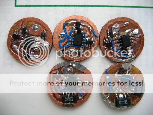
I build programmable flashlight as a hobby so I've done my fair share of soldering here's one of my proto-types
http://img.photobucket.com/albums/v105/rroxas/pop_v113041.jpg
http://img.photobucket.com/albums/v105/rroxas/mag_pdip.jpg
http://img.photobucket.com/albums/v105/rroxas/board-8.jpg
I downloaded both datasheet and will read them tonight this will tell me where the Base, Collector and Emitter terminals are. If I read this correctly on page one of the datasheet pin1=base , pin2=colletor and pin3=emitter.Yes thank you for the info on how to check them with an ohm meter and will subtract that from the reading I get when checking the resistor's value.
@kUmSE, Thank you for the info I will check them aswell as a matter of fact I have some 12/14 pin sockets that I wanted to install so I could just POP those chips in, and gives me a great excuse to fire up my metcal mx-500 station
I build programmable flashlight as a hobby so I've done my fair share of soldering here's one of my proto-types
http://img.photobucket.com/albums/v105/rroxas/pop_v113041.jpg
http://img.photobucket.com/albums/v105/rroxas/mag_pdip.jpg
http://img.photobucket.com/albums/v105/rroxas/board-8.jpg
I got the TIP 102/107s 20 transistors in all from digikey and proceded to replaced them. I took my time and was really carefull not to lift circuit traces and making absolutely sure that most if not all solder was removed from the soundstream pcb by using a combination solder pump and solder wick. I had to flip th board back and forth being carefull not to damage anything especially the 3 led lights located at the lower right side. I started at around 7:00PM and did not finished until 11:00PM
I got to admit the soundstream 405 pcb is well made. It has thick circuit traces and it's built to last, definitely would but more and will be on the lookout.
Here's a pic of the stock board:
High Resolution PICTURE stock board
Here's a pic of it with ten 102s and ten 107 BJT transistors.
High Resolution PICTURE fixed board
WOW! what a difference!
The sound if much cleaner and puncher definitely worth all the time and effort to fix. And yes the subwoofer is not putting out 29 volts anymore Although I've only used and tested it for about an hour I hoping this fixed the problem if it doesn't then the voltage regulators will be next.
Oh yeah, I checked the resistors and they all have .6 or .5 ohm values and non of them where burned or discolored.
BUT I did noticed all of the old TIP 102 BJT transistors had some sort of oily residue comming out of it.
I really cleaned the pcb board and aluminum heat sink and the brownish pad that isolates the transistors from the aluminum plate with rubbing alcohol making sure all old thermal paste are gone. Re-applied new thermal paste so my theory is somehow this oily residue is shorting the amp?
I got to admit the soundstream 405 pcb is well made. It has thick circuit traces and it's built to last, definitely would but more and will be on the lookout.
Here's a pic of the stock board:
An externally hosted image should be here but it was not working when we last tested it.
High Resolution PICTURE stock board
Here's a pic of it with ten 102s and ten 107 BJT transistors.
An externally hosted image should be here but it was not working when we last tested it.
High Resolution PICTURE fixed board
WOW! what a difference!
The sound if much cleaner and puncher definitely worth all the time and effort to fix. And yes the subwoofer is not putting out 29 volts anymore
Although I've only used and tested it for about an hour I hoping this fixed the problem if it doesn't then the voltage regulators will be next. Oh yeah, I checked the resistors and they all have .6 or .5 ohm values and non of them where burned or discolored.
BUT I did noticed all of the old TIP 102 BJT transistors had some sort of oily residue comming out of it.
I really cleaned the pcb board and aluminum heat sink and the brownish pad that isolates the transistors from the aluminum plate with rubbing alcohol making sure all old thermal paste are gone. Re-applied new thermal paste so my theory is somehow this oily residue is shorting the amp?
Thanks swordfish689, I think the key is use the proper soldering tip. I used the STTC-125P metcal tip made by OKI. I highly recommend the metcal mx-500 soldering station to me there's no substitute you can even solder sot-23 components with relative ease and proper lighting is a must.
I played the soundstream amp again for about an hour no problems yet here's the pic of it hooked up in my trunk.
Yep I know, need to design a better amp rack
and proper lighting is a must. An externally hosted image should be here but it was not working when we last tested it.
I played the soundstream amp again for about an hour no problems yet here's the pic of it hooked up in my trunk.
An externally hosted image should be here but it was not working when we last tested it.
Yep I know, need to design a better amp rack

- Status
- This old topic is closed. If you want to reopen this topic, contact a moderator using the "Report Post" button.
- Home
- General Interest
- Car Audio
- Soundstream 405 sub-channel Problem,plz help!