i just replaced some Z44n on the PPI 2150M but LED do not light up.
however, in the process of FETs replacement, i found out that the ground path of the PCB have no conductor(burnt) due at the TS1 area(other side of the PCB).
anything else i can do? i want this to be a learning experience, so money isnt a problem.
btw, i havent replace the gate resistor on the FETs.
btw, thanks for TO-3 and others.
however, in the process of FETs replacement, i found out that the ground path of the PCB have no conductor(burnt) due at the TS1 area(other side of the PCB).
An externally hosted image should be here but it was not working when we last tested it.
An externally hosted image should be here but it was not working when we last tested it.
An externally hosted image should be here but it was not working when we last tested it.
anything else i can do? i want this to be a learning experience, so money isnt a problem.
btw, i havent replace the gate resistor on the FETs.
btw, thanks for TO-3 and others.
profuse007 said:i just replaced some Z44n on the PPI 2150M but LED do not light up.
however, in the process of FETs replacement, i found out that the ground path of the PCB have no conductor(burnt) due at the TS1 area(other side of the PCB).
An externally hosted image should be here but it was not working when we last tested it.
An externally hosted image should be here but it was not working when we last tested it.
An externally hosted image should be here but it was not working when we last tested it.
anything else i can do? i want this to be a learning experience, so money isnt a problem.
btw, i havent replace the gate resistor on the FETs.
btw, thanks for TO-3 and others.
You should find the name of the PWM chip and find the data sheet for it. Figure out which pin is the reset pin and measure to see if the pin is turning the chip off. Is the chip active high or active low?
With powered applied to the amplifier (including remote), what's the DC voltage across the terminals where the missing thermal protector was connected?
If you follow the traces, does it look like the remote line passes through it?
Do both ends of the thermal device go back to the PWM chip? If so, which terminals?
Can you measure the voltage on each pin of the chip and post the readings (meter on DC volts, black lead on main ground terminal)?
Make the results clear. Post them like this:
Pin 1: x volts
Pin 2: x volts...
Re: Re: new FETs installed, no power.
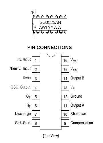
alright, i tried to read about the IC other day(what does IC stand for?) but couldnt quite understand it. the only thing i understood about the chip is that pin 11 and 14 (V-outputs) is connected to teh gate resistors and also to ground (i think....lol), then to the transformer via switchers.
getting back to the PWN, i cant seem to find anything about reset pin. the only thing that i can find about is the push-pull config and it mentiona lil bit about reset. other than that, the pic(click on pic for link) doesnt say which pin is reset.
and if there is a reset pin, how do i test it to see?
An externally hosted image should be here but it was not working when we last tested it.
alright, i tried to read about the IC other day(what does IC stand for?) but couldnt quite understand it. the only thing i understood about the chip is that pin 11 and 14 (V-outputs) is connected to teh gate resistors and also to ground (i think....lol), then to the transformer via switchers.
getting back to the PWN, i cant seem to find anything about reset pin. the only thing that i can find about is the push-pull config and it mentiona lil bit about reset. other than that, the pic(click on pic for link) doesnt say which pin is reset.
and if there is a reset pin, how do i test it to see?
TO-3 said:
You should find the name of the PWM chip and find the data sheet for it. Figure out which pin is the reset pin and measure to see if the pin is turning the chip off. Is the chip active high or active low?
first of all, i use a computer power supply to bench test this so the input is 12v, if not slightly under 12v.
-to answer ur quesiton, the terminal shows 12v, same as the input(from the comp power supply) voltage.
-yes the remote line is connect to the TS1. shows 0v when remote line is disc.
****note: I WILL Reference the TS1 terminal thats connecting to the remote line will be [TSRem], the other one is [TS0].
-the TSRem goes to all of the PWN pins except for 9, 8, 7, and 5, w/ constand resistance.
-the TS0 goes to all of the PWNvpins except for 9 and 8, w/ varrying resistance.
Pin voltage:
1-4 : 12V
5: 11V
6: 12V
7: 11V
8: 11V
9: 6V
10-16: 12V
okay i see some good signs, 11 and 14 have power goin through the gate resistors. it seems like all gates have power, 12V.
alright, those are the only assessment i can make. what else is there?
thanks again, i will make some contribution to this site. do they take paypal?
BTW, TO-3, what do you mean by active low/high?
-to answer ur quesiton, the terminal shows 12v, same as the input(from the comp power supply) voltage.
-yes the remote line is connect to the TS1. shows 0v when remote line is disc.
****note: I WILL Reference the TS1 terminal thats connecting to the remote line will be [TSRem], the other one is [TS0].
-the TSRem goes to all of the PWN pins except for 9, 8, 7, and 5, w/ constand resistance.
-the TS0 goes to all of the PWNvpins except for 9 and 8, w/ varrying resistance.
Pin voltage:
1-4 : 12V
5: 11V
6: 12V
7: 11V
8: 11V
9: 6V
10-16: 12V
okay i see some good signs, 11 and 14 have power goin through the gate resistors. it seems like all gates have power, 12V.
alright, those are the only assessment i can make. what else is there?
thanks again, i will make some contribution to this site. do they take paypal?
Perry Babin said:With powered applied to the amplifier (including remote), what's the DC voltage across the terminals where the missing thermal protector was connected?
If you follow the traces, does it look like the remote line passes through it?
Do both ends of the thermal device go back to the PWM chip? If so, which terminals?
Can you measure the voltage on each pin of the chip and post the readings (meter on DC volts, black lead on main ground terminal)?
Make the results clear. Post them like this:
Pin 1: x volts
Pin 2: x volts...
BTW, TO-3, what do you mean by active low/high?
You need to find the reason that pin 12 is not grounded. It should have read 0 volts. Repair that and then make all of the measurements again.
If remote passes directly through the thermal device (~0 ohms from the remote terminal to the thermal), there's a good chance that it was a simple on/off switch (Normally Closed) and you can solder a jumper across it for testing. I would not recommend installing it in a vehicle without thermal protection.
The gates should not have a constant 12 volts. The most you should read on the gate when the amp is up and running is ~6 volts DC (probably less due to the bandwidth of the meter).
Re: Re: Re: new FETs installed, no power.
Look at pin 10. Because it has a bar over the name it is active low. This pin turns the chip off and is usually tied to the fault-sense circuitry(ie. over-temp, over voltage, DC offset). If this line goes low than the amp will turn off.
Also, if indeed you have 12V on pin 12, as Perry said, that is the first issue that you need to address.
And IC stands for Integrated Circuit.
profuse007 said:An externally hosted image should be here but it was not working when we last tested it.
alright, i tried to read about the IC other day(what does IC stand for?) but couldnt quite understand it. the only thing i understood about the chip is that pin 11 and 14 (V-outputs) is connected to teh gate resistors and also to ground (i think....lol), then to the transformer via switchers.
getting back to the PWN, i cant seem to find anything about reset pin. the only thing that i can find about is the push-pull config and it mentiona lil bit about reset. other than that, the pic(click on pic for link) doesnt say which pin is reset.
and if there is a reset pin, how do i test it to see?
Look at pin 10. Because it has a bar over the name it is active low. This pin turns the chip off and is usually tied to the fault-sense circuitry(ie. over-temp, over voltage, DC offset). If this line goes low than the amp will turn off.
Also, if indeed you have 12V on pin 12, as Perry said, that is the first issue that you need to address.
And IC stands for Integrated Circuit.
sorry ppl but my account, profuse007, is scrwed up and im tring to sort it out w/ the admin.
so, how can i fix problem w/ grounding out to 0V?
im sorry but i dont know whats the on/off switch youre talking about. theres somthing that i havent comprehend about this, plz explain.
btw, this only for educational purposes, i already have a system in my car.
okay i see what you mean about the gate, i forgot about the resistor inline w/ the gate and it should be at ~6v. so what does it say about the PWM output(s) to teh gates?
if im not writing something correctly plz correct me. im really confuse about this.
Perry Babin said:You need to find the reason that pin 12 is not grounded. It should have read 0 volts. Repair that and then make all of the measurements again.
If remote passes directly through the thermal device (~0 ohms from the remote terminal to the thermal), there's a good chance that it was a simple on/off switch (Normally Closed) and you can solder a jumper across it for testing. I would not recommend installing it in a vehicle without thermal protection.
The gates should not have a constant 12 volts. The most you should read on the gate when the amp is up and running is ~6 volts DC (probably less due to the bandwidth of the meter).
Re: Re: Re: Re: new FETs installed, no power.
(moderator: can yall work on my original sn?)
ignore that last post, because i just briefly learn the basic of switchign power supply.
the pin 12 is grounded. i meant to say that probing that pin 12 w/ 12v constant give me +12V.
how do i test to see the step-up voltage from the switching?
where does the LED indicator connected to?
Perry Babin said:You need to find the reason that pin 12 is not grounded. It should have read 0 volts. Repair that and then make all of the measurements again.
If remote passes directly through the thermal device (~0 ohms from the remote terminal to the thermal), there's a good chance that it was a simple on/off switch (Normally Closed) and you can solder a jumper across it for testing. I would not recommend installing it in a vehicle without thermal protection.
The gates should not have a constant 12 volts. The most you should read on the gate when the amp is up and running is ~6 volts DC (probably less due to the bandwidth of the meter).
TO-3 said:
Look at pin 10. Because it has a bar over the name it is active low. This pin turns the chip off and is usually tied to the fault-sense circuitry(ie. over-temp, over voltage, DC offset). If this line goes low than the amp will turn off.
Also, if indeed you have 12V on pin 12, as Perry said, that is the first issue that you need to address.
And IC stands for Integrated Circuit.
okay, i see what you mean. i was looking at a simplified switching power supply diagram and kept thinking of the diagram and how the pin 12 is controlling the FETs through ground. is there something that i didnt understand here?
as far as the test like you described, the voltage is 0VDC. black to ground and probe w/ red, and all pins are at 0VDC.
im very stump right now. i really appologize for being such a newbie. however im trying to read up about the power supply on here.
as far as the test like you described, the voltage is 0VDC. black to ground and probe w/ red, and all pins are at 0VDC.
im very stump right now. i really appologize for being such a newbie. however im trying to read up about the power supply on here.
An externally hosted image should be here but it was not working when we last tested it.
Perry Babin said:You need to post new numbers. Power up the amp (including remote). Place the black meter lead on the amp's ground terminal. Set the meter to DC volts.
Hey Profuse,
Welcome to the forum, anyway. Please don't feel your questions are annoying or in any way bad. That's why we all post here. Some of us to exchange ideas, and some others to learn. This is a learning environment, so don't be afraid to ask.")
This thread could just as easily be in the Power Supplies forum, as it pertains to just that.
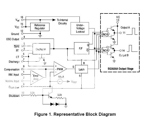
OK, on to my comments: First, what Perry and TO-3 are trying to say is that for this particular PWM chip, the SG3525AN, pin 12 is the ground pin, and obviously, should read 0V. Pins 11 & 14 (the two totem-pole output pins) should read ~6V, because they are switching the MOSFETs at such a high speed (36kHz to 50kHz, or even higher), that if you are trying to measure the FETs' gate voltages with a multimeter, ~6V is what you will read. Instead, try reading them with an oscilloscope, if you have access to one.
Second, the first diagram you showed is from OnSemi's datasheet for the '3525. The type of push-pull circuit shown here is called the half-bridge , because of the way the two N-Channel MOSFETs are connected. This is almost always used for high-voltage inputs, like 120/240VAC, like in your computer PSU, which is the half-bridge type. The type of push-pull circuit in your amp is called the centertap push-pull , most commonly found in 12V (low-voltage) input SMPSs.
Third, Pin 10 of the '3525 is called Active low because, in order to shut the chip down, this pin must be pulled to +12V. Active Low means that the chip is active, or operating, if this pin is held low, or left floating.
Fourth, the last diagram you show is from Rod Elliot's website. This is a good starting place to understanding SMPSs. Although the schematic shown here may not be the exact same as yours, it still should give you a good understanding how yours works.
Hope this clears things up a bit.
Steve
Welcome to the forum, anyway. Please don't feel your questions are annoying or in any way bad. That's why we all post here. Some of us to exchange ideas, and some others to learn. This is a learning environment, so don't be afraid to ask.
This thread could just as easily be in the Power Supplies forum, as it pertains to just that.
OK, on to my comments: First, what Perry and TO-3 are trying to say is that for this particular PWM chip, the SG3525AN, pin 12 is the ground pin, and obviously, should read 0V. Pins 11 & 14 (the two totem-pole output pins) should read ~6V, because they are switching the MOSFETs at such a high speed (36kHz to 50kHz, or even higher), that if you are trying to measure the FETs' gate voltages with a multimeter, ~6V is what you will read. Instead, try reading them with an oscilloscope, if you have access to one.
Second, the first diagram you showed is from OnSemi's datasheet for the '3525. The type of push-pull circuit shown here is called the half-bridge , because of the way the two N-Channel MOSFETs are connected. This is almost always used for high-voltage inputs, like 120/240VAC, like in your computer PSU, which is the half-bridge type. The type of push-pull circuit in your amp is called the centertap push-pull , most commonly found in 12V (low-voltage) input SMPSs.
Third, Pin 10 of the '3525 is called Active low because, in order to shut the chip down, this pin must be pulled to +12V. Active Low means that the chip is active, or operating, if this pin is held low, or left floating.
Fourth, the last diagram you show is from Rod Elliot's website. This is a good starting place to understanding SMPSs. Although the schematic shown here may not be the exact same as yours, it still should give you a good understanding how yours works.
Hope this clears things up a bit.
Steve
thanks for the reply
my assessment to that diagram, right above, is not so great. i can only understand the outputs, pin 11 14 to the primary, and just a lil bit from the secondary, rectifier diodes to the step-up output.
-the process b4 the pin 11 14 start to affect, i dont have a clue to how it would give the output of ~6V. i mean, what makes the the IC(3525) turn on to process?
-about the output of the pin 11 and 14, what is the significant of the voltage (mine will be ~6V) to the Pulse Width? why is it only half or 50%?
btw, once the IC is shut down, does it starts up automatically after a certain threshold?
can any of yall three explain or give me a link on how this chip operate, pin by pin?
http://www.onsemi.com/pub/Collateral/SG3525A-D.PDF
These are this power supply book at radio shack that was very helpful... they don't really make it anymore, but I found them on amazon...
http://www.amazon.com/gp/product/B0...103-6249629-5825442?s=books&v=glance&n=283155
It does the basic power supply, and then goes into a switchmode power supply, real basic stuff... but set up some foundations for me.
profuse said:thanks for the reply
my assessment to that diagram, right above, is not so great. i can only understand the outputs, pin 11 14 to the primary, and just a lil bit from the secondary, rectifier diodes to the step-up output.
-the process b4 the pin 11 14 start to affect, i dont have a clue to how it would give the output of ~6V. i mean, what makes the the IC(3525) turn on to process?
-about the output of the pin 11 and 14, what is the significant of the voltage (mine will be ~6V) to the Pulse Width? why is it only half or 50%?
btw, once the IC is shut down, does it starts up automatically after a certain threshold?
can any of yall three explain or give me a link on how this chip operate, pin by pin?
First, the reason that you should see ~6V is that the output is switching and you are measuring the average voltage. In a nutshell, What you are doing is supplying a consant 12 volts (DC) and and trying to increase the volatge. Well, you can't do much with the !2V that you have because it is only 12V. If you used this to amplifiy your signal, in order to amplify negatively, you would have to cut the voltage in half and swing from a 6V referance. While this could work, we would have to use a transformer to couple the amplifier to the speakers. The transformer coupling is bad for frequency-response and will need to be rather large depending on how much power you want.
A transformer can only amplify a signal instantaneously. That is, when you flip a switch(look at the attached circuit), the voltage is already across the inductor, but the current lags voltage by 90 degrees. With the resistor inline this changes that, but this is for a later discussion. Anyway, when that switch is closed that inductor, for all intensive purposes, instantaneously is not even there. The current in the circuit is regulated by the resistor and the current spikes to the maximum amount dicated by Ohms Law.
The inductor than creates a electrically induced magnetic field that stores, unto itself, a charge (think capacitor).
Anyway, very quickley after the switch is closed, the current tries to settle down to the DC resistace of the coil itself. As the current slows down, the magnetic field around the inductor begins to collape(the stored enery returns to the circuit). Eventually, the circuit reaches an equallibrium point where it is a purley resistive circuit again. The inductor only has a DC resistance and no reactance. The magnetic field is gone.
That is where we introduce a transformer. Applying the same information as above, we can put another electrically isolated inductor against the original inductor(primary) and we have a secondary circuit. As you can see fro the description above, the direct-current is only usefull for the time immediately after we close the circuit. This is where we need to take the !2 volts and chop it into a pulse(alternating-current). The SG3525 acts as a chopper with the chopping frequency controlled by external resistors and capacitors that we will not worry about right now.
The 3525's internal circuit is using the input 12V and switching it on and off creating a pulsed signal. The output pins 11 and 14, if you looked at them with a scope, you will see you have 12V but it is turning on and off(chopped). The chip alone cannot drive a transformer, especially at the current you need, so you use the chip to drive the gates of the MosFETs. The MosFETs, in turn, are in series with the transformer primary and again act as choppers to the 12V. The FETs, though, can pass a significant amount of current through them to induce a stong enough EMF across the secondary winding of the transformer. This electro-magnetic field is now expanding and collapsing so the inductive properties of the primary winding of the transformer now have a benefit.
Great, now you have AC voltage on the seconday winding of the transformer, now what? AC voltage is pretty much useless as it is. We need to turn it back into DC voltage. Using a bridge-rectifier(BR1) we can convert the AC into a pulsed DC current. That is from a referance point of zero we would see a bunch of pulses that look like an amplified version of the outputs of the 3525. We see that the transformer has a center-tap. From the outputs of the bridge-rectifier, we can place caps to the centertap, observing the polarity, and we can create positive and negative voltages with respect to this center-tap(secondary ground). As we add more capacitace across these rails, we smooth and strenghten the rails and minimze noise to our amplifier stages. With added circuitry, we can make other voltages for opamps and such.
I need to get on with my day but I hope this explains what your schematic is showing you. Maybe someone can elaborate on what I wrote or continue on. I'll check in later.

Attachments
I haven't been able to locate one of those old amps but I believe that the missing piece is actually a switch. On the new amps they designate the thermals as Rxxx. That amp used TSx (Thermal Switch ?). If one end of the TS goes directly to the remote input (directly = zero ohms) and the other end goes directly to pins 13 and 15 of the 3525 (possibly through a diode) then it's probably OK to jump it out with a 1 amp fuse (nothing larger).
To get the IC to operate, you need to have ~12 volts on pin 15. This will power the internal components of the IC. On most of the PPI amps, I beleive that pins 13 and 15 are directly connected so getting power to pin 15 should get power to pin 13 which is the positive power source for the totem pole drivers.
When power is applied to pin 13, you should see 5 volts on pin 16 no matter what voltage you have on the other inputs.
If there are no other problems, the amp should then power up andd you should see ~1/2 B+ on the outputs (pins 11 and 14) of the 3525.
When initially powering up the amp, remember that you need to do so through a small fuse (less than 10 amps) or a resistive current limiter (resistor or automotive headlamp).
If you get power to pins 13 and 15 and the 5v regulator output has 5 volts on it but pins 11 and 14 have no voltage, then you should look at the other inputs (like the shutdown terminal).
To answer one of your other questions...
The max duty cycle is 50% for each output. Each is high for 50% of the time and low (near ground) for 50% of the time. They can not be on at the same time. If they were, an almost infinite current would flow through the FETs and destroy them.
These old PPI amps have an unusual power supply that operates mostly in PAM rather than PWM. It won't reduce pulse width unless it gets hot.
The TS1 part is a NTC thermistor - 50k. It should fire up without it.
Simplified schematic
Q2,3 & 4 are a simple op amp that compares rail voltage to Vref and drives the MOSFET gates with a variable voltage.
Scope photo of gate drive
Notice 3.594 Vp-p at idle!
More complete schematic of power supply (this is a 4200, similar to other models)
thanks TO-3[] for give me a track to get on, but im still trying to get into the rail here and itll take me a while. plz dont give up on me.
also, im trying to read up on some of the simplier, low-power power supply instead of these high-power that required MOSFETs.
okay, bridging a +12V to the pin 15 gave pin 16 4.67V. so, what do i need to do to get that IC up permanently w/o having to bridge it?(prolly a weird way to ask but...)
also, pin 11(didnt check 14) only give ~.2V, if thats needed.
what is the next step that i can check?
profuse said:thanks TO-3[] for give me a track to get on, but im still trying to get into the rail here and itll take me a while. plz dont give up on me.
also, im trying to read up on some of the simplier, low-power power supply instead of these high-power that required MOSFETs.
okay, bridging a +12V to the pin 15 gave pin 16 4.67V. so, what do i need to do to get that IC up permanently w/o having to bridge it?(prolly a weird way to ask but...)
also, pin 11(didnt check 14) only give ~.2V, if thats needed.
what is the next step that i can check?
How are you 'bridging' pin 16? You can force the chip on if you short the 2 pins together. Only do this for a functional test. Do not do this if installing the amp. You said this is a learning project so I assume it will not go in a car (at least not yet). Forcing pin 16 high will cause the chip to stay on regardless of the amplifiers state. This means that if the amp has a DC offset and you have a speaker load, you will ruin your speakers. Before you power the amp, you should also try to find a series resistor, if applicable, that goes to pin 16 and pull a lead(remove it from a circuit). Pin 16 may have a 'floating' voltage on it or it may have a voltage from being connected somewhere else. JUST BE CAREFUL!!!
no i forced pin15 to have +12vdc. while having that, i tested the pin 16, and it gives ~5V.
no, this amp will be on my working bench w/ a computer PSU.
perry stated above that the IC need 12v to the pin 13 or 15 to get the IC chip to turn on and i forced it to turn on. however, how do i make the pin 13 or 15 to get power?
no, this amp will be on my working bench w/ a computer PSU.
perry stated above that the IC need 12v to the pin 13 or 15 to get the IC chip to turn on and i forced it to turn on. however, how do i make the pin 13 or 15 to get power?
- Status
- This old topic is closed. If you want to reopen this topic, contact a moderator using the "Report Post" button.
- Home
- General Interest
- Car Audio
- new FETs installed, no power.