Hi there, I am new to the forum and am putting together a basic stereo from some old unused parts.
I have a rockford fosgate 250a2 that stopped working a few years ago. It no longer powers up. I remember that I had it mounted under a seat and someone shoved there foot under the seat and kicked the ground out and caused it to short on the 12V.
I was planning on opening it up and checking the capacitors and transistors. If anyone is familiar with where the problem lies, I would greatly appreciate it as my desoldering skills are not that good.
Thanks
It should have done nothing more than blown the fuse in the power wire feeding the amp. If there were no fuse, it could have burned a trace in the amp.
If you can take some voltage measurements while the amp is connected to a power supply, I'd be willing to try to help.
If you have a digital camera, post or email me a clear photo of the amp.
If you can take some voltage measurements while the amp is connected to a power supply, I'd be willing to try to help.
If you have a digital camera, post or email me a clear photo of the amp.
It did blow the fuse on the power line. After replacing the fuse and reattaching the ground, the amp never worked.
I can measure some voltages when hooked up to a power supply. At which points would you like me to measure.
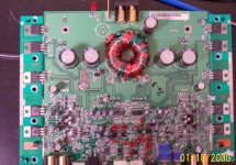
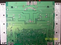
I have attached the pics of the amp. One of the front side, and one of the back side.
There is one capacitor missing when I took the pics. I thought it was bad but turned out to be fine. The burn marks on the board are from removing it, it cleaned up fine. I only had a super fat tip when I was desoldering it.
Let me know if you want bigger pics of the amp.
I can measure some voltages when hooked up to a power supply. At which points would you like me to measure.
I have attached the pics of the amp. One of the front side, and one of the back side.
There is one capacitor missing when I took the pics. I thought it was bad but turned out to be fine. The burn marks on the board are from removing it, it cleaned up fine. I only had a super fat tip when I was desoldering it.
Let me know if you want bigger pics of the amp.
Attachments
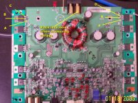
Measure the resistance points A-B and D-E (amp not connected to any source of power). If you get something greater than ~1meg ohms, power the amp up through a 5 amp fuse (nothing larger). Measure the DC voltage at all points in the photo and post the results. The black laed will remain on the ground terminal of the amp for all measurements. Also post the voltage on the remote and B+ inputs (again, black lead on the ground terminal).
Attachments
- Status
- This old topic is closed. If you want to reopen this topic, contact a moderator using the "Report Post" button.
- Home
- General Interest
- Car Audio
- Repairing Rockford Fosgate 250a2