Since if blew the fuse with the rectifiers out I decied to pull the output and power transistors. They all eneding up being good so i double check all my solder points useing a meter with ohms. And tryed it with the rectifiers in and The fuse didn't blow i conected the remote and the fuse still doesn't blow.
After turn the amp on through the 10amp fuse the protection led stays on. if u leave the amp on it sounds like a relay clicks on.
After turn the amp on through the 10amp fuse the protection led stays on. if u leave the amp on it sounds like a relay clicks on.
I hooked up the power and now my protection lead lights up and then goes off. if u leave it hooked up a relay clicks then once u disconnect the power the protection lead blinks and the relay clicks back.
Testing volts but there were non guessing that's because the protection led lights then goes off.
Testing volts but there were non guessing that's because the protection led lights then goes off.
If there was no DC voltage across the tabs of the output transistors, it means that the power supply is not operating (I'm assuming that you've reinstalled the rectifiers).
It's normal for the protection LED to come on then go off. When the protection LED goes off, the green LED should light.
The click is the muting relay. It prevents the amp from passing turn-on/off transients to the speakers. It's supposed to turn on delayed and turn off instantly as the remote is applied/removed.
i was reading on the web about switching power supplys and was woundering if it's possible to test the for power after the rectifers to see if im getting the correct amount. or if there's anyway to tell if my power transistors are switching. i testing the b+ going into the coil and it's good.
Could my drivers be bad on switching chip?
Could my drivers be bad on switching chip?
With power applied to the amp (including remote), set you meter to AC volts and measure the voltage across the tabs of the 2 sets of power supply FETs. There are 2 sets of 4 FETs. You need to measure across the two sets. Touch one meter lead to the FET on one end of the line of FETs and the other lead to the FET on the other end. If you read something very near zero volts, the power supply is not running. I never use a voltmeter for this so I tried it with several meters I have here and there were readings from ~10VAC to ~35VAC.
To measure the output of the power supply, you would need to get one meter lead on the 3rd leg of one of the IRF640s and one meter lead on the 3rd leg of one of the IRF9640s. It's going to be difficult to do with the amp mounted in the heatsink. If the power supply is running and you short-circuit the test point to the heatsink clamps, you risk doing more damage. If you had a reading of zero AC volts in the previous test (across the power supply FETs), there is no reason to test for power supply output on the output transistors.
The drivers could be bad but defective drivers almost always cause the amp to draw excessive current because they are not driving the gate voltage back to ground when the FET needs to be switched off.
What meter do you have? If I can find a similar one, maybe I can see what it reads on a working amp.
Apply power to the amp (including remote) and measure the voltage AC and DC on each pin of the TL594 (494) driver IC. Black lead on ground for all tests. Download a datasheet for the IC if you don't know how the pins are numbered. You'll have to do it from the back of the driver board so double-check the pin numbering.
Post the values like this:
Pin 1:
AC = xxx volts
DC = xxx volts
Pin 2:
AC = xxx volts
DC = xxx volts
TL494
I got zero for all ac volts
Pin 1
DC =0
Pin 2
DC =5.00
Pin 3
DC =0.06
Pin 4
DC =0.58
Pin 5
DC =0.16
Pin 6
DC =3.71
Pin 7
DC =0
Pin 8
DC =12.67
Pin 9
DC =0.58
Pin 10
DC =0.58
Pin 11
DC =12.67
Pin 12
DC =12.67
Pin 13
DC =5.00
Pin 14
DC =5.00
Pin 15
DC =5.00
Pins 15 and 16 look to be bridge together by something
but it doesn't carry current
Pin 16
DC =0
What's the model numbers on the meters. I'm trying to make sense of the numbers but I need to know precisely what meters you have. If I can find a similar meter, I can check an amp here with it. That way it will be easier to understand the numbers you have posted.
With the DC voltages you have, the chip should be producing pulses on pins 9 and 10. The voltage on pin 3 is relatively low so the chip should be running close to the maximum possible duty cycle. That would normally produce a higher DC reading than 0.6v (~1/2 B+ is normal at max duty cycle).
Try the other meter to see if you get different numbers. If the numbers vary by more than ~10%, post the new values. Check both AC and DC.
New results
Radio shack meter
15-Range Digital Multimeter
Model: 22-810 | Catalog #: 22-810
The following test were done with a commerical electric multimeter HDM350(not the radio shack meter)
I found the other radio shack meter to be falty
Pin 1
Ac- Flashing neg sign no voltage
Dc-0
Pin 2
Ac-10.4
Dc-5
Pin 3
Ac-0
Dc-.06
Pin 4
Ac-.9
Dc-.61
Pin 5
Ac-.1
Dc-.16
Pin 6
Ac-7.5
Dc-3.7
Pin 7
Ac-flashign neg sign no voltage
Dc-
Pin 8
Ac-27.3
Dc-12.67
Pin 9
Ac-.8
Dc-.58
Pin 10
Ac-.8
Dc-.58
Pin 11
Ac-27.2
Dc-12.67
Pin 12
Ac-27.2
Dc-12.67
Pin 13
Ac-10.3
Dc-5
Pin 14
Ac-10.4
Dc-5.00
Pin 15
Ac-10.4
Dc-5
Pin 16
Ac-Flashing neg sign No voltage
Dc-0
The meter arrived and it looks like it's reading about the same as yours.
Pin 5 is a concern. It should be higher. I read 1.47 VDC and 2.7 VAC on a working amplifier with the CE meter. The only thing connected to that pin is a timing capacitor. I've never seen a timing cap leak (electrically) to pull the voltage down. It looks like the IC is defective but it's not going to be easy to change.
Does it look like there are any contaminants, corrosion or any foreign material near pin 5 on either side of the board?
They're likely using that cap (between 1 and 4) to slow the response of the dead time input.
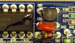
There's a mylar capacitor (orange) on near the end of the chip (see attached image). Does it look damaged in any way?
Did you clean the area around the blown drivers?
What's the condition of the board around that orange cap?
Are there any possible solder bridges in that area?
There's a mylar capacitor (orange) on near the end of the chip (see attached image). Does it look damaged in any way?
Did you clean the area around the blown drivers?
What's the condition of the board around that orange cap?
Are there any possible solder bridges in that area?
Attachments
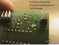
Pic #1 Back of PWM board.
I have the drivers removed in this pic to clean and check everything. Does the middle Pin (collector) on the driver closest to the end of the board connect to the yellow area as i marked
--This would connect the two drivers middle pin(collector)--
As the driver farest to the left connects to this area
-----This also seams to connect to pin 7 on the IC---
Attachments
- After reinstalling the drives and checking traces i installed the pwm board back into the amp and powered it up.
- the amp powers up and the green power led lights with the protection led off
- after leaveing the amp on the muteing curcit clicks and about 2 secs after that the 10 amp fuses blows(just slightly)
- the amp powers up and the green power led lights with the protection led off
- after leaveing the amp on the muteing curcit clicks and about 2 secs after that the 10 amp fuses blows(just slightly)
- Status
- This old topic is closed. If you want to reopen this topic, contact a moderator using the "Report Post" button.
- Home
- General Interest
- Car Audio
- Memphis 1000D Transistor Blowing