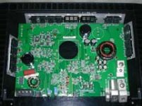
hi i keep seeing posts regarding blown these types of amplifiers, and now that one of my own is blown i'm curious what steps we are taking to repair them. I have it opened and since it's not authorized RF dealer purchased i don't give a f*, but anyway the piece that was odd after it blew it's main fuse and began it's improper working condition the two prongs to the terminal for +/- on the fan wires was burnt on the bottom of the board, so this was removed. Tried to power it on and it hasn't changed its condition. I don't see any blown MOSFETs and am curious what steps i should take to begin repairs. As I don't have a job right now i cannot afford to pay to repair it, and it won't sell for nearly half as much as i paid for it now.

i know these pictures are tiny as *****. email me jbimbane@hotmail.com if you want big 2meg fullsize pics! thx!
Hi
Usually the fans are fed with 12V directly, that means it´s unlikely that the fan or the fan- curcuits would cause the main fuse to blow.
When main fuses blow most of the time Mosfets are blown or the control curcuit that drives the mosfets is not working properly. This can cause all mosfets to "stay open" all the time and thus generating a short through the transformer coils.
Because of the high current draw the amp has now it´s hard to start measuring to determine where the fault comes from.
Usually amplifiers have working protection curcuits (ok, those curcuits are often too slow to prevent a damage if something goes wrong when driving the amplifier hard but they usullay keep the SMPS off when there is a real short in the music section.) These type of curcuits even work in cheap amplifiers. So I would assume there´s a fault in the SMPS.
The bigger mosfets often don´t look burned when they are fried. When I start fixing amplifiers I always resolder all the power parts first. A lot of faults are caused by bad solder joints.
Then I use a diode-tester (if your multimeter doesn´t have this use the ohmmeter function) and check the big rectifier diodes. Those are connected to the output coils of the transformer. Check the diodes´legs . If you take a closer look at the diodes, you see that there are two diodes in one housing. And when you compare the diodes you see that there are diode(s) that has(ve) two connected anodes, the other(s) has(ve) two connected catodes. There musnt´be short if you test each anode-to-catode way. ( each measurement will slowly encrease resistance(or cause the diode tester to increase the voltage you read at the mutimeter) , that´s because your meter chrages the big capacitors, wait a few seconds until the capacitors are charged) but if there is a short , take the diodes out and test the diodes again. if there is still a short you have faulty diodes. If the diodes are ok check the curcuit board with the diode tester. If you find the short there you could have faulty capacitors (unlikely) or something in the music section is damaged.
Once finished with the rectifier diodes check the mosfet legs for a direct short. If you find a short at a mosfet, it is burned. If there is one faulty mosfet I´d suggest to take them all out off the curcuit board.
Here is a small test curcuit for N-channel mosfets.
When all the fets are out you can connect power to the amplifier. Use a small 12V power supply that will only deliver 2 Amps . That´s enough to drive a car amplifier w/o load. Also connect a 2Ohm /10W power-resistor in series with the +12V cable. This way you prevent all parts from burning if therewould still be a fault in the amp (in case of a short, the amp would draw a huge current, the current causes a voltage drop at the resistor thus limiting the max. current that could ever flow, you can also use a 12V/10W light bulb for that)
When the mosfets are out of the curcuit board connect the power as mentionend. Connect 12V to RMT. The amp should try to power up.
Use a scope and connect it to GND and to each gate- resistor (each mosfet has a gate resistor, usually something around 10-100 Ohms) . You should see a nice square wave at every gate resistor. If it´s there, the smps controller curcuits should have survived. If there is nothing or the signals look scrambled you can trace your way backwards to find out why the smps controller doesn´t power up / causes a bad signal. Usually the controller-IC does not drive the mosfets directly. there small signal transistors in line to drive the mosfets. When mosfets burn, sometimes the small transistors also burn.
Also, please check what kind of smps-controller is used . There should be a small IC , usually near the transformer. I know with SMD-parts it´s hard to read what´s written on the parts. Check for numbers if you find a "494" or a "2525" or "3525" ... those are the most common controller -ICs used in car amplifiers.
Let us know what you find out.
Steph
Usually the fans are fed with 12V directly, that means it´s unlikely that the fan or the fan- curcuits would cause the main fuse to blow.
When main fuses blow most of the time Mosfets are blown or the control curcuit that drives the mosfets is not working properly. This can cause all mosfets to "stay open" all the time and thus generating a short through the transformer coils.
Because of the high current draw the amp has now it´s hard to start measuring to determine where the fault comes from.
Usually amplifiers have working protection curcuits (ok, those curcuits are often too slow to prevent a damage if something goes wrong when driving the amplifier hard but they usullay keep the SMPS off when there is a real short in the music section.) These type of curcuits even work in cheap amplifiers. So I would assume there´s a fault in the SMPS.
The bigger mosfets often don´t look burned when they are fried. When I start fixing amplifiers I always resolder all the power parts first. A lot of faults are caused by bad solder joints.
Then I use a diode-tester (if your multimeter doesn´t have this use the ohmmeter function) and check the big rectifier diodes. Those are connected to the output coils of the transformer. Check the diodes´legs . If you take a closer look at the diodes, you see that there are two diodes in one housing. And when you compare the diodes you see that there are diode(s) that has(ve) two connected anodes, the other(s) has(ve) two connected catodes. There musnt´be short if you test each anode-to-catode way. ( each measurement will slowly encrease resistance(or cause the diode tester to increase the voltage you read at the mutimeter) , that´s because your meter chrages the big capacitors, wait a few seconds until the capacitors are charged) but if there is a short , take the diodes out and test the diodes again. if there is still a short you have faulty diodes. If the diodes are ok check the curcuit board with the diode tester. If you find the short there you could have faulty capacitors (unlikely) or something in the music section is damaged.
Once finished with the rectifier diodes check the mosfet legs for a direct short. If you find a short at a mosfet, it is burned. If there is one faulty mosfet I´d suggest to take them all out off the curcuit board.
Here is a small test curcuit for N-channel mosfets.
An externally hosted image should be here but it was not working when we last tested it.
When all the fets are out you can connect power to the amplifier. Use a small 12V power supply that will only deliver 2 Amps . That´s enough to drive a car amplifier w/o load. Also connect a 2Ohm /10W power-resistor in series with the +12V cable. This way you prevent all parts from burning if therewould still be a fault in the amp (in case of a short, the amp would draw a huge current, the current causes a voltage drop at the resistor thus limiting the max. current that could ever flow, you can also use a 12V/10W light bulb for that)
When the mosfets are out of the curcuit board connect the power as mentionend. Connect 12V to RMT. The amp should try to power up.
Use a scope and connect it to GND and to each gate- resistor (each mosfet has a gate resistor, usually something around 10-100 Ohms) . You should see a nice square wave at every gate resistor. If it´s there, the smps controller curcuits should have survived. If there is nothing or the signals look scrambled you can trace your way backwards to find out why the smps controller doesn´t power up / causes a bad signal. Usually the controller-IC does not drive the mosfets directly. there small signal transistors in line to drive the mosfets. When mosfets burn, sometimes the small transistors also burn.
Also, please check what kind of smps-controller is used . There should be a small IC , usually near the transformer. I know with SMD-parts it´s hard to read what´s written on the parts. Check for numbers if you find a "494" or a "2525" or "3525" ... those are the most common controller -ICs used in car amplifiers.
Let us know what you find out.
Steph
- Status
- This old topic is closed. If you want to reopen this topic, contact a moderator using the "Report Post" button.