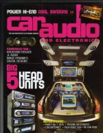
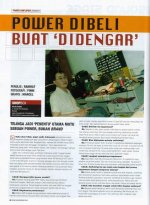
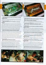
Thanks guys 
It feels great tobe able to get into International level magazine, when usually the reviews are from the commercial products, coming from $$$loaded companies.
But I have to build about 100's of power amp topologies, until the later ones have the sound quality that makes the magazine calls for the interview
I can tell you, there are alot-lot-lot-lot-lot-lot-lot-lot.....of knowledge here in this forum. They are floating around, maybe some will notice it, maybe some don't read at all
Once there is a guy making SMPS based on the pcb on my website. One day the bank capacitor exploded infront of his face (fortunately, he didn't hurt, he just shocked). He emailed me telling me that. Latter I found out that he put the capacitor polarity +/- backwards. I imagine how dangerous it is for someone who hasn't experience with soldering electronics, jumping straightly to such thing as making SMPS.
Since then I feel uneasy to encourage people to make things based on my design. It's not that I'm cheap with my designs (Infact I'm happy if someone else builds my design, you can look at my website), but, I really feel uneasy after that. I understand now why some website put "Build at your own Risk" before you see any schematic.
I feel I can get sue'd only by providing the right schematic, but not writing "Build at your own Risk" or "Do not make this if you haven't got any experience with electronics"
Banned
Joined 2002
Ok Man
I understand what you write about build at your own risk.
That good, but how we will improved in design car amplifders if we cant get eny new ideas from other desighners around the world.
Sow if you update your schematic on your site please updeate the notification on this mail.
Also update with more projects your site.
Buy for now
OK,
First :
BUILD AT YOUR OWN RISK
Second :
AND FOR EXPERIENCED BUILDERS ONLY
Third :
I don't have schematic for this, please don't ask me. The only schematic I have is in my head . You can generate the schematic from the pcb.
The pcb is in Protel 2.7 format.
There are 3 pcbs, the main pcb, the driver pcb, the PWM pcb.
I make the little pcb's as "plugable", so you can try various topologies by changing the driver pcb only.
The VBE multiplier works fine for bias about 7mA in the VAS. So, if you design your own driver card, set about 7mA in the VAS, or you will have to change the VBE multiplier resistors.
The core for the SMPS I use 1cm2 window area toroidal ferrite core, gives me 4x2turns for primary and 10x2turns for secondary (about +/-30VDC rails)
I cannot attach the file here, they have wrong type extension.
http://valveaudio.tripod.com/diy/DIYDRIVE.PCB
http://valveaudio.tripod.com/diy/DIYMAIN.PCB
http://valveaudio.tripod.com/diy/DIYPWM.PCB
Use right click, "save target as"
First :
BUILD AT YOUR OWN RISK
Second :
AND FOR EXPERIENCED BUILDERS ONLY
Third :
I don't have schematic for this, please don't ask me. The only schematic I have is in my head
The pcb is in Protel 2.7 format.
There are 3 pcbs, the main pcb, the driver pcb, the PWM pcb.
I make the little pcb's as "plugable", so you can try various topologies by changing the driver pcb only.
The VBE multiplier works fine for bias about 7mA in the VAS. So, if you design your own driver card, set about 7mA in the VAS, or you will have to change the VBE multiplier resistors.
The core for the SMPS I use 1cm2 window area toroidal ferrite core, gives me 4x2turns for primary and 10x2turns for secondary (about +/-30VDC rails)
I cannot attach the file here, they have wrong type extension.
http://valveaudio.tripod.com/diy/DIYDRIVE.PCB
http://valveaudio.tripod.com/diy/DIYMAIN.PCB
http://valveaudio.tripod.com/diy/DIYPWM.PCB
Use right click, "save target as"
Sorry, it should be small letters
http://valveaudio.tripod.com/diy/diydrive.pcb
http://valveaudio.tripod.com/diy/diymain.pcb
http://valveaudio.tripod.com/diy/diypwm.pcb
.......oops
I think I need help here. In the server, the extension is correct (.pcb). Why is when I try to download it, my Windows automaticly change it to .htm? My protel doesn't recognize this .htm file. How to make it still .pcb file when downloaded?
Anybody can help?
- Status
- This old topic is closed. If you want to reopen this topic, contact a moderator using the "Report Post" button.
- Home
- General Interest
- Car Audio
- My car amp in CarAudio magazine


