Re: Source of Transformer / Core
hi, i've been looking for it here in my country...and i found out that those apc ups have it because it has an inverter 12v to 220volts....and probably all ups and inverter are a good source....hope you find one...good luck
cfog88 said:Hi!
I have seen quite a few references to winding a ferrite core, but haven't yet managed to find a good source for ferrite cores. Where did you get yours?
Thanks,
Chjris
hi, i've been looking for it here in my country...and i found out that those apc ups have it because it has an inverter 12v to 220volts....and probably all ups and inverter are a good source....hope you find one...good luck
Look in dead computer power supplies.
As above you will find the needed cors in computer power supplies.
Mark
Source of Transformer / Core Post #26
As above you will find the needed cors in computer power supplies.
Mark
Re: Source of Toroid Cores
Chris,
Try Amidon Incorporated out of California. For power conversion, they stock ferrite toroid cores in the #77 material that can handle up to 1.5kW at 40kHz! For energy storage (as in the output inductor in an SMPS), they stock powdered-iron toroid cores in the #26 material up to 5.200" (O.D.)!
Their entire catalogue can be downloaded from their website, at:
www.amidoncorp.com
I have made many SMPSs with toroids from Amidon for both the power transformer and the output inductor, with great results.
Steve
cfog88 said:Hi!
I have seen quite a few references to winding a ferrite core, but haven't yet managed to find a good source for ferrite cores. Where did you get yours?
Thanks,
Chjris
Chris,
Try Amidon Incorporated out of California. For power conversion, they stock ferrite toroid cores in the #77 material that can handle up to 1.5kW at 40kHz! For energy storage (as in the output inductor in an SMPS), they stock powdered-iron toroid cores in the #26 material up to 5.200" (O.D.)!
Their entire catalogue can be downloaded from their website, at:
www.amidoncorp.com
I have made many SMPSs with toroids from Amidon for both the power transformer and the output inductor, with great results.
Steve
Another SMPS schematic
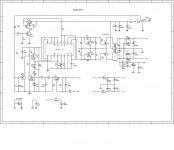
Hello everyone especially to RISTO80.....i have posted here the schematic diagram below......of JBL-50 SMPS and i would like to know if you have a way to design the pcb layout like the one you posted upon the modification of KAC-716 SMPS.....i think its the same but different in mosfet used...Kindly look it up for our references... thank you
Hello everyone especially to RISTO80.....i have posted here the schematic diagram below......of JBL-50 SMPS and i would like to know if you have a way to design the pcb layout like the one you posted upon the modification of KAC-716 SMPS.....i think its the same but different in mosfet used...Kindly look it up for our references... thank you
Attachments
I'm surprised to see so many amps with no regulation on the switchmode.
If you look at the Elliot Sound Products web page, their switchmode is regulated ( can be seen at http://sound.westhost.com/project89.htm#fig9)
The only drawback with this one is that there is no temperature shutdown on their design, which i think i'd want if it was in a car.
If you look at the Elliot Sound Products web page, their switchmode is regulated ( can be seen at http://sound.westhost.com/project89.htm#fig9)
The only drawback with this one is that there is no temperature shutdown on their design, which i think i'd want if it was in a car.
help!!!
hi RISTO80
I built the smps of kenwood amp as per ur schematic and layout .I used a toroidal stripped off from an old car amplifier (35-0-35, primary 6+6 and secondary 12+12) though the output voltage is ok but as soon as i connect the load (amplifier) the bridge rectifier diodes 35Amp/400volt start becoming hot. I didnt use the remote transistor c925 and a1534 as i have connected the +12v directly to the ic. I dont have the scope to determine the frequency wave.What could be the problem.
regards
Hi
Hello to everybody
I am glad to see that the interest of this project is very big.
Firs of all now days my project is finish I now days I am testing with 12 sub speaker and it works very good. I will put digital and more clearance picture when I find data cable for Minolta “Damage X”.
I will answer for some questions:
The switching frequency is determined with RT-resistor 16k and CT-capacitor 1nf witch are connected with pin 6 and pin 5. The approach is done with equation Fclk= 1/(RTxCT). So RT=16k and CT=0.001uf and Fclk=62.5Khz.You can read more from valveaudio site.
I used standard ferrite core with primary turns 2x4 turns and secondary 2x12 turns and I have +/-37 volts.
The schematic of JBL-50 SMPS will not work wit amp of that design. Better is to build the smps of Kenwood because is more powerful and better designed.
About the regulation of SMPS. Most trade marks like Kenwood used non regulation system because is more powerful and the fets is not so hot.
And for aman. The toroid and winding is good. Used the transistors for remote control don’t connected direct to +12 volts to pin of TL494.
For bridge rectifier you used regular of fast recovery bridge rectifier. You must used fast bridge rectifier the regular one will always burn.
Also check the wirings from bridge and the PCB because the PCB is not design for bridge rectifier. Check if you connected correctly.
By for know and if you have any questions put them on this site.
smps working
Hi Risto80
I made the smps work.I used the fast diode now MUR22 and correctrly inserted the 1000p in the output of the toroidal which i wrongly connected before. I used it with my existing amplifier and it sounded awesome,smps is really powerful and the mosfets and the toroidal are cool.
However there is something wrong in the pcb tracks for the diodes MUR22 i.e the secondary of the toroidal should go to the center pins of the diodes and the. so i also corrected the tracks on my pcb. I also used another toroidal with more secondary and it gave me 56-0-56 volts.I m thinking of using it for an amp using 2* a1943/c5200 working on 56-0-56 for which i have only made the pcb and not filled it with components yet. What are ur suggestions??
regards
Aman
smps checked
Hi Arasuk
I tested the smps with a car amp using tip2955/3055 in the output. I first disconnected its own 35-0-35 from its smps supply ,just disconnected the jumper to the amp section. I got the toroidal core from the lajpat rai market in delhi.The shop has got every king of ferrite core.I bought 3-4 pieces of the cores of 2cm and 3cm inner diameter.There are 6+6 turns in the primary and 12+12 in the secondary.I dont remember the wire guage but i used double wires of 20guage i think for the primary and single wire of 19guage for the secondary. sorry......i am not sure abt the wire guage. But if u wanna really wanna know the guage i will tell u.
regards
Aman
Aman_4g@yahoo.com
- Status
- This old topic is closed. If you want to reopen this topic, contact a moderator using the "Report Post" button.
- Home
- General Interest
- Car Audio
- Finished Car Amplifier schematic + PCB based on Kenwood KAC-716