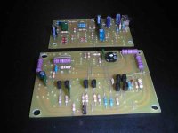
Finished Car Amplifier schematic + PCB based on Kenwood KAC-716
This Project is “Car amplifier” and its basic parts- SMPS, Amplifier, Preamplifier and Protection circuit witch are based on originally schematic from service manual of Kenwood Car amplifier KAC-716.
I have work on this project about five mounts and it WORKS.
From originally schematic of KAC-716, I have made PCB’s separately for SMPS, Amplifier, Preamplifier and Protection sow it can be build very easy.
All electronics capacitor from Amplifier, Preamplifier and Protection are 50 volts range. Input capacitors 2x 3300uf/16volts and output capacitors 2x2200uf/50volts and additionally 2x1500uf/50volts should have 105 C temperature ranges.
All documents are in PDF format and JPEG. The PCB’s are in original sizes.
The SMPS is not regulated so the output voltage will depend on turns ratio in ferrite core. I used 2 x 4 turn’s primary wire and for second it depends of why high will be the output voltage.
By choosing a proper resistance for resistor R222/1W connected with pin 6 of UPC1237 we must set up maximum current of 80mA. The valley of R222 depends of internal resistance of relay and supply. For better calculation download the datasheet for UPC1237 form Internet-Read the note for using UPC1237 and you can understand what kind of other protections are given from this IC’s and used in this design.
The amplifier has specifications:
Max Power Output (4ohm)………………………….. 240Wx1 (at 100Hz)
Rated Power Output (4ohm)………………………....120Wx1 (0.08% THD at 100Hz)
Rated Power Output (4ohm)………………………... 160Wx1 (0.8% THD at 100Hz)
Signal to Noise Ratio……………………………….. 100dB
Sensitivity (MAX)………………………………….. 0.15V
Sensitivity (MIN)…………………………………... 4.0V
Input Impedance…………………………………….10Kohm
Low-Pass Filter (12dB/oct.) ………………………. 30-200Hz (Variable)
Operating Voltage…………………………………..14,4V (11~16V allowable)
Current Consumption (1 kHz, 10% THD, 4ohm)…..15A
Know I will put schematic and PCB for this project and these days also I will put pictures of this project.
Attachments
I study your SMPS PCB layout and I see you add one tranzistor and some P-CON pin. What's that? I didn's saw that on shematic.
And question about amplifier. Is it possible to use with 2 ohm, or can I make two of this module and bridge it. And what's nominal power for this amplifier?
Thanks
And question about amplifier. Is it possible to use with 2 ohm, or can I make two of this module and bridge it. And what's nominal power for this amplifier?
Thanks
Hello
Hello
First about calculating the number of primary and secondary windings, you must refer to valveaudio site and project of making car amplifier from ESP projects site.
Second. The P-CON pin from SMPS is connected to Protection PCB.I forgot to put P-CON pin on SMPS schematic. P-CON pin is supply voltage for IC PWM TL494. When you turn off the amplifier, it sometimes causes a shock-off noise, there for is necessary to break off the relay and then to keep the power amplifier apart from speaker at the moment when car amp will go off. This is basic function of P-CON pin. Also the TH1-2k2 witch you will put on a heatsink, will prevent of over-hitting the amplifier.
The Feedback pin from Protection PCB is connected to Amplifier pin feedback for feedback the signal witch will get through relay.
The amplifier is Kenwood and I have made it exactly as the originally just separately PCB’s and it can drive 2 ohm speaker.
Max Power Output (4ohm)………………………….. 240Wx1 (at 100Hz)
Rated Power Output (4ohm)………………………....120Wx1 (0.08% THD at 100Hz)
Rated Power Output (2ohm)………………………... 160Wx1 (0.8% THD at 100Hz)
Yes I have seen all 3 of the schematic/pcb lay out. But none of them shows how to get +/-15V, +/-40 V from a standard car battery. I have also read a toroidal transformer was mentioned earlier in this post. This transformer I believe could be part of the inverter that produces those voltages. Can anybody give me some more informations on this? of which I thank you very much.
You don't cache thing?
Here is shematic of smps:
http://www.diyaudio.com/forums/attachment.php?s=&postid=648843&stamp=1116957078
and here is pcb layout for smps:
http://www.diyaudio.com/forums/attachment.php?s=&postid=648849&stamp=1116957686
Smps -or switch mode power suply is DC-DC converter which convert 12 V car batery voltage to +/ 40V in our case.
+/15 V you get from power amp when you paralel zener diode to input voltage for amp. In this case you can drain max 500 ma from zener.
If you still don't cache thing then you must learn basic of power managment which I can't explain you here
- Status
- This old topic is closed. If you want to reopen this topic, contact a moderator using the "Report Post" button.
- Home
- General Interest
- Car Audio
- Finished Car Amplifier schematic + PCB based on Kenwood KAC-716