I had been posting about a problem with my car amp and sub in Loudspeakers forum "My almost finished sub" , and the thread went to deep into amplifier so I start a new thread here to ask u guys about the non speakers stuff.
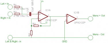
Ok, the following picture is the summing block I am going to build. However, how do I build a power supply for it to use in a car, and how do I determine what gain I want? I used some info form my CHy Moy headphone amp knowledge to draw this, so I am not sure will this work for car audio. Plz give me some advices.
Ok, the following picture is the summing block I am going to build. However, how do I build a power supply for it to use in a car, and how do I determine what gain I want? I used some info form my CHy Moy headphone amp knowledge to draw this, so I am not sure will this work for car audio. Plz give me some advices.
Attachments
S.C asked:
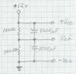
You can build a surprisingly simple and effective power supply for powering op amps in a car... I hate to even post this... But it really does work.
All you have to do is make a voltage divider with two equal resistors, filter them with capacitors, and use the node where they join as your reference voltage.
(See the attached scan)
Choose identical resistor values that draw significantly more current than the IC's you are using, so the referance voltage will be stable. I usually used 100 ohms, but values as high as 1k could be reasonable for a low current IC. 100 ohms will be sufficient to easily run a couple of quad amps. Be sure the power rating for the resistor is adequate for the current it will draw.
A more precise supply can be made using op amps to derive the reference, but they will have to handle the supply current through their outputs. Besides, there's really no need to complicate things for this type of job.
This supply will leave a DC component in the output signal, simply use a decoupling capacitor in series with the output of the last IC to eliminate that.
You can use a transistor or relay in front of the divider to switch the supply on/off with the remote lead.
As far as the summing circuit goes, I've always been more comfortable summing into the inverted input because of it's virtual ground characteristic. Without the benefit of test equipment to verify performance, I feel this is the best way to ensure other impedances are influencing the circuit as little as possible.
I have been known to be wrong.
If you choose to use the inverted method, simply use an inverting follower for your output buffer. You can use that for your gain stage as well, if you want gain. I would suggest minimal gain ( no more than 2 or so) because you don't want to approach the 6 volt rails you created with the supply above.
By the way, nice job with the Dremel tool. Is that MDF you cut with that thing? You really should invest in a cheap jigsaw to save yourself some effort!
Tim
However, how do I build a power supply for it to use in a car, and how do I determine what gain I want?
You can build a surprisingly simple and effective power supply for powering op amps in a car... I hate to even post this... But it really does work.
All you have to do is make a voltage divider with two equal resistors, filter them with capacitors, and use the node where they join as your reference voltage.
(See the attached scan)
Choose identical resistor values that draw significantly more current than the IC's you are using, so the referance voltage will be stable. I usually used 100 ohms, but values as high as 1k could be reasonable for a low current IC. 100 ohms will be sufficient to easily run a couple of quad amps. Be sure the power rating for the resistor is adequate for the current it will draw.
A more precise supply can be made using op amps to derive the reference, but they will have to handle the supply current through their outputs. Besides, there's really no need to complicate things for this type of job.
This supply will leave a DC component in the output signal, simply use a decoupling capacitor in series with the output of the last IC to eliminate that.
You can use a transistor or relay in front of the divider to switch the supply on/off with the remote lead.
As far as the summing circuit goes, I've always been more comfortable summing into the inverted input because of it's virtual ground characteristic. Without the benefit of test equipment to verify performance, I feel this is the best way to ensure other impedances are influencing the circuit as little as possible.
I have been known to be wrong.
If you choose to use the inverted method, simply use an inverting follower for your output buffer. You can use that for your gain stage as well, if you want gain. I would suggest minimal gain ( no more than 2 or so) because you don't want to approach the 6 volt rails you created with the supply above.
By the way, nice job with the Dremel tool. Is that MDF you cut with that thing? You really should invest in a cheap jigsaw to save yourself some effort!
Tim
Attachments
So is the refrence voltage will go to ground, and what is the point of puting a decouple cap in front of the resistors like (c)Choose identical resistor values that draw significantly more current than the IC's you are using, so the referance voltage will be stable. I usually used 100 ohms, but values as high as 1k could be reasonable for a low current IC. 100 ohms will be sufficient to easily run a couple of quad amps. Be sure the power rating for the resistor is adequate for the current it will draw.
A more precise supply can be made using op amps to derive the reference, but they will have to handle the supply current through their outputs. Besides, there's really no need to complicate things for this type of job.
An externally hosted image should be here but it was not working when we last tested it.
from headwizeSo I need to put one more decoupleing cap on the output while I already had one on the input.This supply will leave a DC component in the output signal, simply use a decoupling capacitor in series with the output of the last IC to eliminate that.
I don't uinderstand the pt of this. Is the summing block will on all the time even my key wasn't there? I don't understand how to wire the battery to this summing block and amp too. Do I take a lead out of the stock head unit harness to get the voltage, or some other ways?You can use a transistor or relay in front of the divider to switch the supply on/off with the remote lead.
What do you mean by a follower? Is my IC B a follower, and will it work as the circuit I draw? Or I need some adjustment on it?If you choose to use the inverted method, simply use an inverting follower for your output buffer. You can use that for your gain stage as well, if you want gain. I would suggest minimal gain ( no more than 2 or so) because you don't want to approach the 6 volt rails you created with the supply above.
I hope I have spare money on tools too, drill press, saw, and router. If time and money is premited, I am willing to learn how to use mill, but the fact is I am only a spoiled college student who had never work before.By the way, nice job with the Dremel tool. Is that MDF you cut with that thing? You really should invest in a cheap jigsaw to save yourself some effort!
Tim
from Immo_G:
Absolutely. That's why you have to use a decoupling cap on the output. Something in the 1 to 10uF range, electrolytic, and observe proper polarity. This will act as a subsonic filter of course, and limit slew rate as AC coupling does. Nothing is free!
If you know the input impedance of your amp, use it for R in the formula:
f=1/(2piRC)
to determine the subsonic filter frequency. If the one output is driving two inputs of the amp, that would be:
f=1/(piRC)
S.C wrote:
The idea of the circuit is to give you a reference other than ground. Ground becomes your (-) supply rail, V/2 (or about 6 volts) becomes your reference, and +12v becomes your (+) supply rail.
The reference (shown as ground in those drawings) is NOT grounded (not in car audio). The drawings are a little misleading. In the case of (a) or (b), it wouldn't matter. But in (c) it would short circuit the negative supply rail. The only thing connected to the reference are the connections to ground on the schematic you're using for the summing block.
Just connect the shield for the output RCA's to the input RCA's shield.
Notice on the drawing (c) isn't using batteries for a DC supply, it's using rectified AC. Therefore the capacitor on the input.
I don't see the one on the input as critical. One on the output is in this case, unless there is one internally in your amp.
Well, you can run this circuit from the accessory lead (on/off with the key) but it would be best to turn it on and off along with the amp. I don't remember, are you using the stock head unit? I'll post a drawing (later tonight or tomorrow) on how to incorporate the turn-on circuit into the power supply, and include battery and amp in the diagram. It would help to know which head unit you are using and if stock, what type of car.
A follower is actually called a "voltage follower", and simply follows the input signal. At first glance, it may seem pointless. They're very useful to isolate your circuits from the effects of external impedances. Therefore the name "buffer." Line drivers are buffers designed usually to drive long cables. An inverting follower mirrors the input signal to provide an output 180º out of phase with the input.
I'll have to look back at the schematic to be sure it's strictly a buffer...
Tim
The headunits RCA ground is grounded (maybe via a 1k resistor, maybe not) to the car body, would this interfere with your circuit?
Absolutely. That's why you have to use a decoupling cap on the output. Something in the 1 to 10uF range, electrolytic, and observe proper polarity. This will act as a subsonic filter of course, and limit slew rate as AC coupling does. Nothing is free!
If you know the input impedance of your amp, use it for R in the formula:
f=1/(2piRC)
to determine the subsonic filter frequency. If the one output is driving two inputs of the amp, that would be:
f=1/(piRC)
S.C wrote:
So is the refrence voltage will go to ground, and what is the point of puting a decouple cap in front of the resistors like (c)
The idea of the circuit is to give you a reference other than ground. Ground becomes your (-) supply rail, V/2 (or about 6 volts) becomes your reference, and +12v becomes your (+) supply rail.
The reference (shown as ground in those drawings) is NOT grounded (not in car audio). The drawings are a little misleading. In the case of (a) or (b), it wouldn't matter. But in (c) it would short circuit the negative supply rail. The only thing connected to the reference are the connections to ground on the schematic you're using for the summing block.
Just connect the shield for the output RCA's to the input RCA's shield.
Notice on the drawing (c) isn't using batteries for a DC supply, it's using rectified AC. Therefore the capacitor on the input.
So I need to put one more decoupleing cap on the output while I already had one on the input.
I don't see the one on the input as critical. One on the output is in this case, unless there is one internally in your amp.
I don't uinderstand the pt of this. Is the summing block will on all the time even my key wasn't there? I don't understand how to wire the battery to this summing block and amp too. Do I take a lead out of the stock head unit harness to get the voltage, or some other ways?
Well, you can run this circuit from the accessory lead (on/off with the key) but it would be best to turn it on and off along with the amp. I don't remember, are you using the stock head unit? I'll post a drawing (later tonight or tomorrow) on how to incorporate the turn-on circuit into the power supply, and include battery and amp in the diagram. It would help to know which head unit you are using and if stock, what type of car.
What do you mean by a follower? Is my IC B a follower, and will it work as the circuit I draw? Or I need some adjustment on it?
A follower is actually called a "voltage follower", and simply follows the input signal. At first glance, it may seem pointless. They're very useful to isolate your circuits from the effects of external impedances. Therefore the name "buffer." Line drivers are buffers designed usually to drive long cables. An inverting follower mirrors the input signal to provide an output 180º out of phase with the input.
I'll have to look back at the schematic to be sure it's strictly a buffer...
Tim
These are really handy for quick wood work
Handheld scroll saw at loewes. They can be had for $20-$40, and are pretty handy...takes a steady hand though")
Handheld scroll saw at loewes. They can be had for $20-$40, and are pretty handy...takes a steady hand though
Sorry for skipped on day of post. I recieved my amp yesterday, and I took my time on gaming after my 3rd chemistry test. So I'm back again, and I need to do a little shopping for installing the amp and try the bridge mode first. Also, I am not really sure how the sub out will act like, if it comes out to be the same signals from left and right then everything will be fine. Then I just need to connect it to the amp and drive sub seperatly. However, if this is really true, I can also change this block to a true buffer or blanced line output device. So the posts here are still useful for this application, and keep posting. Then I will test the sub outs later when I am installing my amp.
Car: 96 Red Honda Civic Coupe
HU: Kenwood KDC-MPV5205 MP3/CD reciever:
- Preout Level/load (During Disc Play):
2000 mV /10 kOhm
- Preout impedance:
< 600 Ohm
Amp: Blaupunkt PA2150 Class T Amplifier
"Birth Certificate"
1.RMS output power : bridged (4Ohm) @ 1.0% THD
= Min power in any channel 480 Wrms.
2.RMS output power : non-bridged (2Ohm) @ 1.0% THD
= Min power in any channel 180 Wrms.
3.@ Rated power, bridged mode - 51 Amps
4.@ Rated power, non-bridged mode - 32 Amps
5.@ 33% rated power, non-bridged mode - 11 Amps
6.@ 10% rated power, non-bridged mode - 5 Amps
7.@ idle - 1.5 Amps
8.@ Rated power, non-bridged
A weighted
Average Value for all channels >100db
Test conditions: Loads 4Ohm resistive in all modes unless noted, voltage=13.8 Volts DC.
Input impendance - 10k ohms
Input signal voltage control range - 0.3-6.0 vrms
Trigger line current draw - @20mA
Subwoofer driver: JBL LC-S1200W
specifications
Recommended Amplifier Power Range: 12-200W
Sensitivity: 91dB
Frequency Response: 40Hz¡V500Hz
Mounting Depth: 5" (127mm)
Cut-out Diameter: 10-3/4" (273mm)
Thiele and Small Parameters
Nominal Impedance: 4 Ohms
Revc: 3.45 Ohms
Fs: 27.4Hz
Vas: 124 Liters
Qms: 3.18
Qes: 0.37
Qts: 0.33
Mms: 109.2g
Levc: 2.2mH
Sealed-Enclosure Specifications
Enclosure Volume 1.25 cu. ft. (35.88 Liters)
Vented-Enclosure Specifications
Enclosure Volume 1.75 cu. ft. (49.54 Liters)
Port Diameter 4" (101.6mm)
Port Length 10-3/4" (273mm)
Bandpass-Enclosure Specifications
Sealed-Chamber Volume 1.25 cu. ft. (35.88 Liters)
Vented-Chamber Volume 1 cu. ft. (28.31 Liters)
Port Diameter 4" (101.6mm)
Port Length 6" (152.4mm)
I think this will be more than enough details for you to answer my following questions regarding to your post. I had been reading different car audio site lately, and I found one extermely useful. So I understand I can get power supply form the circaret(spelling) lighter, or seting up a distrobution block from batt + voltage for this purpose. What is the differences and advantage on these ways? For the gain calculation, I think I will set the final summing block output voltage not more than 5. Since My amp max is 6 vrms, I think <5v will be save and the sound will be pretty decent. Am I right? And how can I calculate the final voltage which coming out from the active summing block with a voltage follower? I will redraw the sch, so this question can leave it by now.
So is it not a good idea to turn on everything at the same time with the remote power from the reciever?
Is it because the pop it created by the rush of the voltage flow?
I want to test the bridged mode and drive the sub in series to see how its work, and the package came with a high line level adapter, should I use it? Do you guys use normal RCA 2 males-2 males too? Or should I leave it for the summing block since its lead the female leads are wires only (easy assemble for PCB).
 section and this
Are you talking about my design too?tsmith1315 said:from Immo_G:
Absolutely. That's why you have to use a decoupling cap on the output. Something in the 1 to 10uF range, electrolytic, and observe proper polarity. This will act as a subsonic filter of course, and limit slew rate as AC coupling does. Nothing is free!
If you know the input impedance of your amp, use it for R in the formula:
f=1/(2piRC)
to determine the subsonic filter frequency. If the one output is driving two inputs of the amp, that would be:
f=1/(piRC)
So C1 will not do the job. CAn I take it out, and only run one cap on the end of IC BI don't see the one on the input as critical. One on the output is in this case, unless there is one internally in your amp.
Ok here is the spec of my car and the whole system:Well, you can run this circuit from the accessory lead (on/off with the key) but it would be best to turn it on and off along with the amp. I don't remember, are you using the stock head unit? I'll post a drawing (later tonight or tomorrow) on how to incorporate the turn-on circuit into the power supply, and include battery and amp in the diagram. It would help to know which head unit you are using and if stock, what type of car.
Car: 96 Red Honda Civic Coupe
HU: Kenwood KDC-MPV5205 MP3/CD reciever:
- Preout Level/load (During Disc Play):
2000 mV /10 kOhm
- Preout impedance:
< 600 Ohm
Amp: Blaupunkt PA2150 Class T Amplifier
"Birth Certificate"
1.RMS output power : bridged (4Ohm) @ 1.0% THD
= Min power in any channel 480 Wrms.
2.RMS output power : non-bridged (2Ohm) @ 1.0% THD
= Min power in any channel 180 Wrms.
3.@ Rated power, bridged mode - 51 Amps
4.@ Rated power, non-bridged mode - 32 Amps
5.@ 33% rated power, non-bridged mode - 11 Amps
6.@ 10% rated power, non-bridged mode - 5 Amps
7.@ idle - 1.5 Amps
8.@ Rated power, non-bridged
A weighted
Average Value for all channels >100db
Test conditions: Loads 4Ohm resistive in all modes unless noted, voltage=13.8 Volts DC.
Input impendance - 10k ohms
Input signal voltage control range - 0.3-6.0 vrms
Trigger line current draw - @20mA
Subwoofer driver: JBL LC-S1200W
specifications
Recommended Amplifier Power Range: 12-200W
Sensitivity: 91dB
Frequency Response: 40Hz¡V500Hz
Mounting Depth: 5" (127mm)
Cut-out Diameter: 10-3/4" (273mm)
Thiele and Small Parameters
Nominal Impedance: 4 Ohms
Revc: 3.45 Ohms
Fs: 27.4Hz
Vas: 124 Liters
Qms: 3.18
Qes: 0.37
Qts: 0.33
Mms: 109.2g
Levc: 2.2mH
Sealed-Enclosure Specifications
Enclosure Volume 1.25 cu. ft. (35.88 Liters)
Vented-Enclosure Specifications
Enclosure Volume 1.75 cu. ft. (49.54 Liters)
Port Diameter 4" (101.6mm)
Port Length 10-3/4" (273mm)
Bandpass-Enclosure Specifications
Sealed-Chamber Volume 1.25 cu. ft. (35.88 Liters)
Vented-Chamber Volume 1 cu. ft. (28.31 Liters)
Port Diameter 4" (101.6mm)
Port Length 6" (152.4mm)
I think this will be more than enough details for you to answer my following questions regarding to your post. I had been reading different car audio site lately, and I found one extermely useful. So I understand I can get power supply form the circaret(spelling) lighter, or seting up a distrobution block from batt + voltage for this purpose. What is the differences and advantage on these ways? For the gain calculation, I think I will set the final summing block output voltage not more than 5. Since My amp max is 6 vrms, I think <5v will be save and the sound will be pretty decent. Am I right? And how can I calculate the final voltage which coming out from the active summing block with a voltage follower? I will redraw the sch, so this question can leave it by now.
So is it not a good idea to turn on everything at the same time with the remote power from the reciever?
Is it because the pop it created by the rush of the voltage flow?
I want to test the bridged mode and drive the sub in series to see how its work, and the package came with a high line level adapter, should I use it? Do you guys use normal RCA 2 males-2 males too? Or should I leave it for the summing block since its lead the female leads are wires only (easy assemble for PCB).
I think the IC B have few mistake, and I am going for NI confriguation. And what is the different betweenA follower is actually called a "voltage follower", and simply follows the input signal. At first glance, it may seem pointless. They're very useful to isolate your circuits from the effects of external impedances. Therefore the name "buffer." Line drivers are buffers designed usually to drive long cables. An inverting follower mirrors the input signal to provide an output 180º out of phase with the input.
I'll have to look back at the schematic to be sure it's strictly a buffer...
An externally hosted image should be here but it was not working when we last tested it.
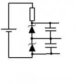
? I notice the different input method, but what is the different, and adventage?What is that triangle thing? diodes?sss said:hello guys
dont u think the next config willgive u better resolts ?
I will think about it, but I really want a drill press first.Hybrid fourdoor said:These are really handy for quick wood work
Handheld scroll saw at loewes. They can be had for $20-$40, and are pretty handy...takes a steady hand though
S.C said:
What is that triangle thing? diodes?
those are zener diodes , u can use 4.7V or 5.1V zener diodes
instead of the resistor network and get a much better power supply
I'm kinda jumping in, in the middle here, but why does this need to be active?
L/R summing is as simple as 2 resistors. Of course adding phase switches is a whole different matter, but won't your sub amp have phase and if not, why don't you just swap the polarity of the speaker?
What you are doing is very simple.
The way you are doing it is not.
L/R summing is as simple as 2 resistors. Of course adding phase switches is a whole different matter, but won't your sub amp have phase and if not, why don't you just swap the polarity of the speaker?
What you are doing is very simple.
The way you are doing it is not.
So all your doing is putting an iso-barik sub in your car? Powering it off your deck, and then an amp?
And your deck has a sub-output?
So easy..
No need to line sum, the deck will do that for you, or if your worried, just use one channel of the deck out, and then split that to the right and left of the amp. (You should be able to test by just turning balance all to one side, if both sub outs still have power, then well it's summing in the deck.)
Attachments
officeboy said:So all your doing is putting an iso-barik sub in your car? Powering it off your deck, and then an amp?
And your deck has a sub-output?
So easy..
No need to line sum, the deck will do that for you, or if your worried, just use one channel of the deck out, and then split that to the right and left of the amp. (You should be able to test by just turning balance all to one side, if both sub outs still have power, then well it's summing in the deck.)
First, this is my first time working with a car, and I am not sure what will the deck's sub out will like.
Sub out mode: Left out to left channel sub, right out to right channel sub.
Or Sub out mode: Left and Right in the same signal. And your "balance" trick is quite clever that I only need one channel, but will it sound good? And the summing part is not sure yet. Anyway I will decide rather or not continue this little add-on after I tested the HU.
Second, I think the "active" setting is better because the hu voltage out is pretty low, and the summing will gonna degade the sound too. I also have some OPA2132 laying around, so I want to use them for something. And I finally understand what is buffer. Hehe, I'm too dumb.
Third, I have a little bit of timeto spend on exploring the way of buffer, and circuit design.
Forth, this is all I can think of untill your "balance" trick
Tonight, I watched The day after tomorrow, and the chronico of ridick. It is always why I am posting this at 4:37 West coast time. I got all my wires and connectors, but the fuse and holder. I need to go to homedepot to buy the 6 ga cable for the power supply, and some connectors, but I cna't find 50A fuse and no holder with 6 ga wire wide. I went to radio shack, pet boys, autozone, and homedepot. No luck, none of them carry 50A fuse and holder with 6 ga.
Looks like I'm behind on following up... I'm an old man with kids, so sometimes this kind of thing has to take a back seat.
Anyway, S.C, you have some good suggestions from officeboy and sss.
sss wrote:
(zener supply schematic)
I'm surprised no one else has posted alternatives, or even flames. That's why I said:
Just be sure current draw isn't too high for the zeners to pass safely. I seriously doubt you'd hear any difference between the two in such a simple application.
S.C asked about decoupling cap highpass results:
and:
Yep, and yep. I still haven't really reviewed your original schematic, because of your posted alternative...
Officeboy's suggestions are right-on, I didn't realize your head unit would have a sub output. That was just beggining to happen when I exited car audio years ago! The ones I used were so-so performers, and I almost always opted to add an external crossover for proper frequency selection.
But given your concerns and the spirit of DIY and learning, let's trudge on. I humbly suggest:
-install the amp in normal fashion, use the deck's sub outputs.
-wire the woofers in series, bridging the amp mono into 8 ohms.
-build your circuit, insert it into the system and evaluate the difference.
The second schematic you posted is mixes R+L into the inverting (-) input of the op amp. The inverting input has a very low impedance, hence impedances external to your circuit have less effect on its function. It does invert phase.
All you need to do is change a couple of R values, add the capacitor on the output, and this circuit should work perfectly.
The first IC does the mixing. Resistor tolerance on the R&L lines in need to be as small as practical so their signals mix in equal proportions. The feedback R (3k on your drawing) will set the gain for that section. Gain (ratio of output to input voltage) is simply equal to the ratio of feedback to input resistances.
You can add gain right there, and skip the second IC if you'd like. You have a 2V input and want a 5V output. That's an increase, or gain of 2.5x. For gain of 2.5, use:
feedback R = 2.5x input R's.
If you want to keep the second IC in place and re-invert phase to 0º. You can add gain there instead the same way, with the ratio of feedback/input resistors.
The 100 ohm resistors are there to insure stability in driving cables. If you mount this circuit near the amp and use short RCA cables, they shouldn't be necessary, but it would hurt nothing to keep them in place.
Hope that gives you something to chew on.
I wouldn't run this circuit directly off the remote output. They are low-current outputs for switching only. I'd use a relay or transistor to switch battery power.
Tim
Anyway, S.C, you have some good suggestions from officeboy and sss.
sss wrote:
dont u think the next config willgive u better resolts
(zener supply schematic)
I'm surprised no one else has posted alternatives, or even flames. That's why I said:
I hate to even post this... But it really does work.
Just be sure current draw isn't too high for the zeners to pass safely. I seriously doubt you'd hear any difference between the two in such a simple application.
S.C asked about decoupling cap highpass results:
Are you talking about my design too?
and:
So C1 will not do the job. CAn I take it out, and only run one cap on the end of IC B
Yep, and yep. I still haven't really reviewed your original schematic, because of your posted alternative...
Officeboy's suggestions are right-on, I didn't realize your head unit would have a sub output. That was just beggining to happen when I exited car audio years ago! The ones I used were so-so performers, and I almost always opted to add an external crossover for proper frequency selection.
But given your concerns and the spirit of DIY and learning, let's trudge on. I humbly suggest:
-install the amp in normal fashion, use the deck's sub outputs.
-wire the woofers in series, bridging the amp mono into 8 ohms.
-build your circuit, insert it into the system and evaluate the difference.
The second schematic you posted is mixes R+L into the inverting (-) input of the op amp. The inverting input has a very low impedance, hence impedances external to your circuit have less effect on its function. It does invert phase.
All you need to do is change a couple of R values, add the capacitor on the output, and this circuit should work perfectly.
The first IC does the mixing. Resistor tolerance on the R&L lines in need to be as small as practical so their signals mix in equal proportions. The feedback R (3k on your drawing) will set the gain for that section. Gain (ratio of output to input voltage) is simply equal to the ratio of feedback to input resistances.
You can add gain right there, and skip the second IC if you'd like. You have a 2V input and want a 5V output. That's an increase, or gain of 2.5x. For gain of 2.5, use:
feedback R = 2.5x input R's.
If you want to keep the second IC in place and re-invert phase to 0º. You can add gain there instead the same way, with the ratio of feedback/input resistors.
The 100 ohm resistors are there to insure stability in driving cables. If you mount this circuit near the amp and use short RCA cables, they shouldn't be necessary, but it would hurt nothing to keep them in place.
Hope that gives you something to chew on.
I wouldn't run this circuit directly off the remote output. They are low-current outputs for switching only. I'd use a relay or transistor to switch battery power.
Tim
Ok, I found out the output of my headunit is both mono even though it is connected with two RCA. So I don't need the summing anymore, but I need buffer! I tested the sub with my amp and headunit, and I notice the lacking of power. I turned the sub volume in my hu all the way to 15, but I can only notice the bass from the trunk in a high moderate level which is disturbing because the tweester is way too loud. Although I had already set the gain all the way down to 0.3Vrms, it is hard to identify the bass from where. Maybe this good cuz it means the system act as a whole. Anyway, I think building a buffer to go with this system will be a good idea cuz I can have a better chance to play around setting.
P.S: I have a question about the sub. The sub enclouse vibrate when I put too less stuffing in it, and play accratly and clear. However, the sub sound unclear, blury, and kinda slow when I put a whole bag of stuffing 20 oz polyester fiberfil in it. It is like you talking in the water, and I am hearind it across a glass.How can I achieve an tight, accrate bass sound with how much stuffing?
P.S: I have a question about the sub. The sub enclouse vibrate when I put too less stuffing in it, and play accratly and clear. However, the sub sound unclear, blury, and kinda slow when I put a whole bag of stuffing 20 oz polyester fiberfil in it. It is like you talking in the water, and I am hearind it across a glass.How can I achieve an tight, accrate bass sound with how much stuffing?
IF your gain is all the way up, and you still don't have enough volume. Either something is broken, or something isn’t hooked up right.
Considering your sub/amp combo should be good for 113db you should be able to hear that, esp after adding in cabin/room gain.
You sure you have the phase of your drivers right? Maybe pull the top speaker and see if it gets louder with just one hooked up.
Considering your sub/amp combo should be good for 113db you should be able to hear that, esp after adding in cabin/room gain.
You sure you have the phase of your drivers right? Maybe pull the top speaker and see if it gets louder with just one hooked up.
Yes everything is right. I even tried the difference of different driver being out of phase, nd I like the driver inside out of phase more. I hear the bass that but I just want a bit more, cuz the volume is kinda low when it is in low volume. I start noticeing it clearly when I turned up the volume to 25 which I had never done it when I was driving. or Maybe all this is because of too much stuffing inside which make the bass wide spread(spelling maybe) and unaccurate nor tight. How can do I know when is enough stuffing? Am I just keep adding it just after the enclouse won't vibrate anymore? an How can I mount this round sub on the trunk?
Stuffing isn't there to keep the enclosure from vibrating; it's there to kill resonant frequencies bouncing around in the box. I would say that a very small amount of stuffing would do ya just fine.
As to the box vibrating a lot, well IMO a single sonotube without bracing is not adequate for a sub box.
To hold the sub down you could use some type of strapping screwed to the wall of your trunk. Either nylon webbing type straps, or metal “plumbers tape” kinda strapping should work fine.
As to the box vibrating a lot, well IMO a single sonotube without bracing is not adequate for a sub box.
To hold the sub down you could use some type of strapping screwed to the wall of your trunk. Either nylon webbing type straps, or metal “plumbers tape” kinda strapping should work fine.
Yead, that true, but what is the most vibratable component on this sub is the outside cone and the outside frame. I don't know why. I can reduce the vibrateion noise by sitting on the endcup and the outside subwoofer drive face down, but some thing still vibrate between the cone and the frame. However, i will add 8 wood stick bracing inside the sonotube to re-enforce the tube like a drum, but the brancing will decreace its volume a bit below the factory spec (.75 sq ft.) Maybe I will build a bit longer on next year haha.
- Status
- This old topic is closed. If you want to reopen this topic, contact a moderator using the "Report Post" button.
- Home
- General Interest
- Car Audio
- Power supply for a active summing block.